3D (three-dimensional) printing system structure

A system structure and 3D printing technology, applied in the field of 3D printing, can solve problems such as reducing the quality or pass rate of processed parts, limiting the size of processed parts, and affecting processing accuracy, so as to reduce the difficulty of manufacturing and testing, reduce motion modulation, and improve The effect of machining accuracy

Inactive Publication Date: 2014-06-04
UNIV OF SCI & TECH OF CHINA
View PDF4 Cites 51 Cited by
  • Summary
  • Abstract
  • Description
  • Claims
  • Application Information

AI Technical Summary

Problems solved by technology

Since the same axis is used as the sliding axis and the rotating axis at the same time, the device will be affected by various interference factors when it is working, thus affecting the machining accuracy
When the 3D printer head works for a long time, the shortcomings will be more prominent, which greatly reduces the quality or pass rate of the processed parts
[0003] At the same time, most of the existing small 3D printers use L-shaped unilateral suspension to provide Z-axis movement. This device only uses a vertical screw to drive the stage to move in the Z-axis direction.
Due to the unilateral suspension, the device is not easy to be stable when working, and it is easy to deform under load-bearing conditions, thus affecting the processing accuracy
When the size of the stage is made too large, the disadvantages will be more prominent, so in principle, the size of the workpiece is limited

Method used


Image

  • 3D (three-dimensional) printing system structure
  • 3D (three-dimensional) printing system structure
  • 3D (three-dimensional) printing system structure

Examples


Embodiment Construction

[0026] Examples of the present invention are described below. But the following examples are limited to explain the present invention, and the protection scope of the present invention should include the whole content of claim, and through following embodiment, those skilled in the art can realize the whole content of claim of the present invention.

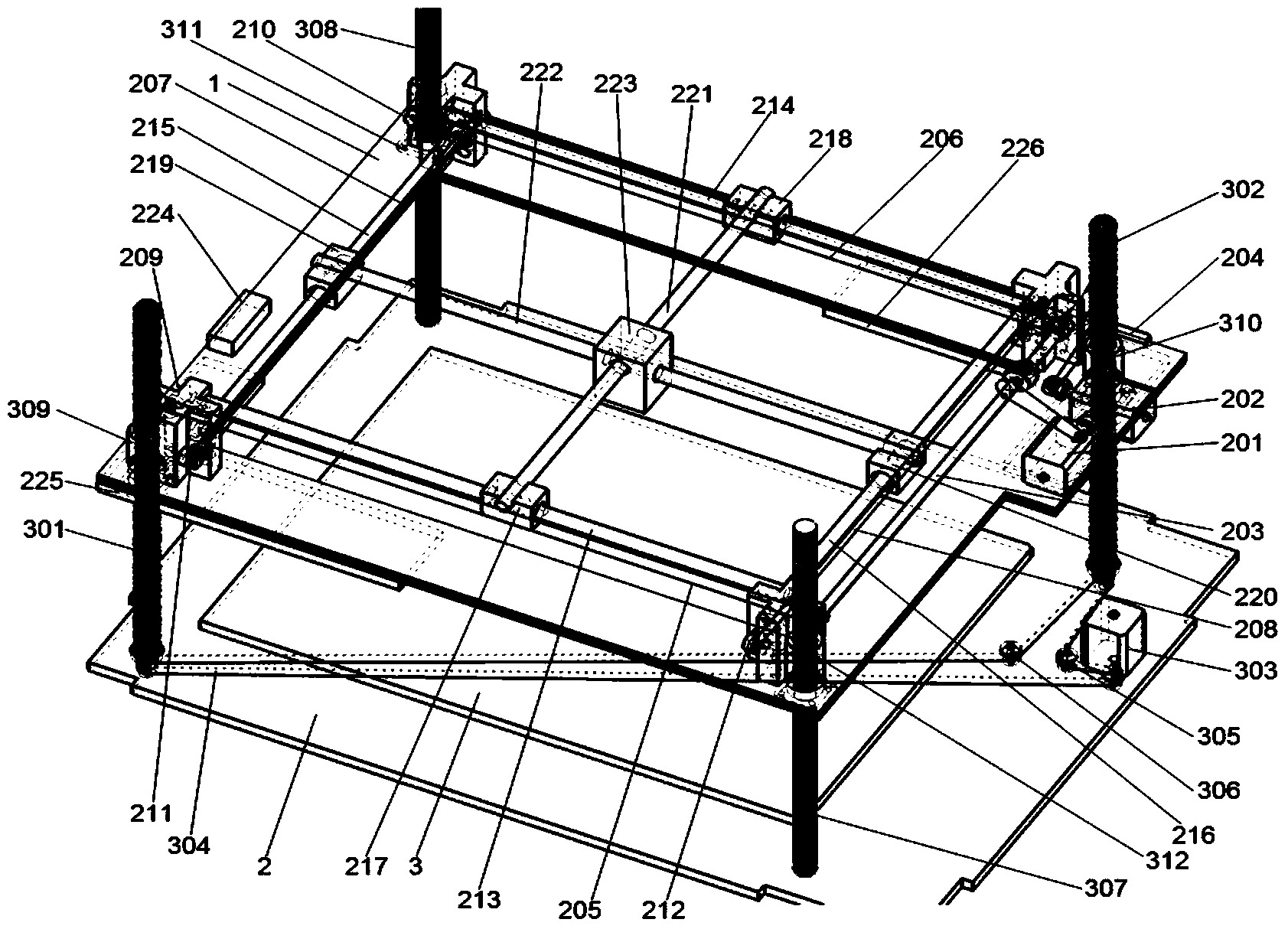
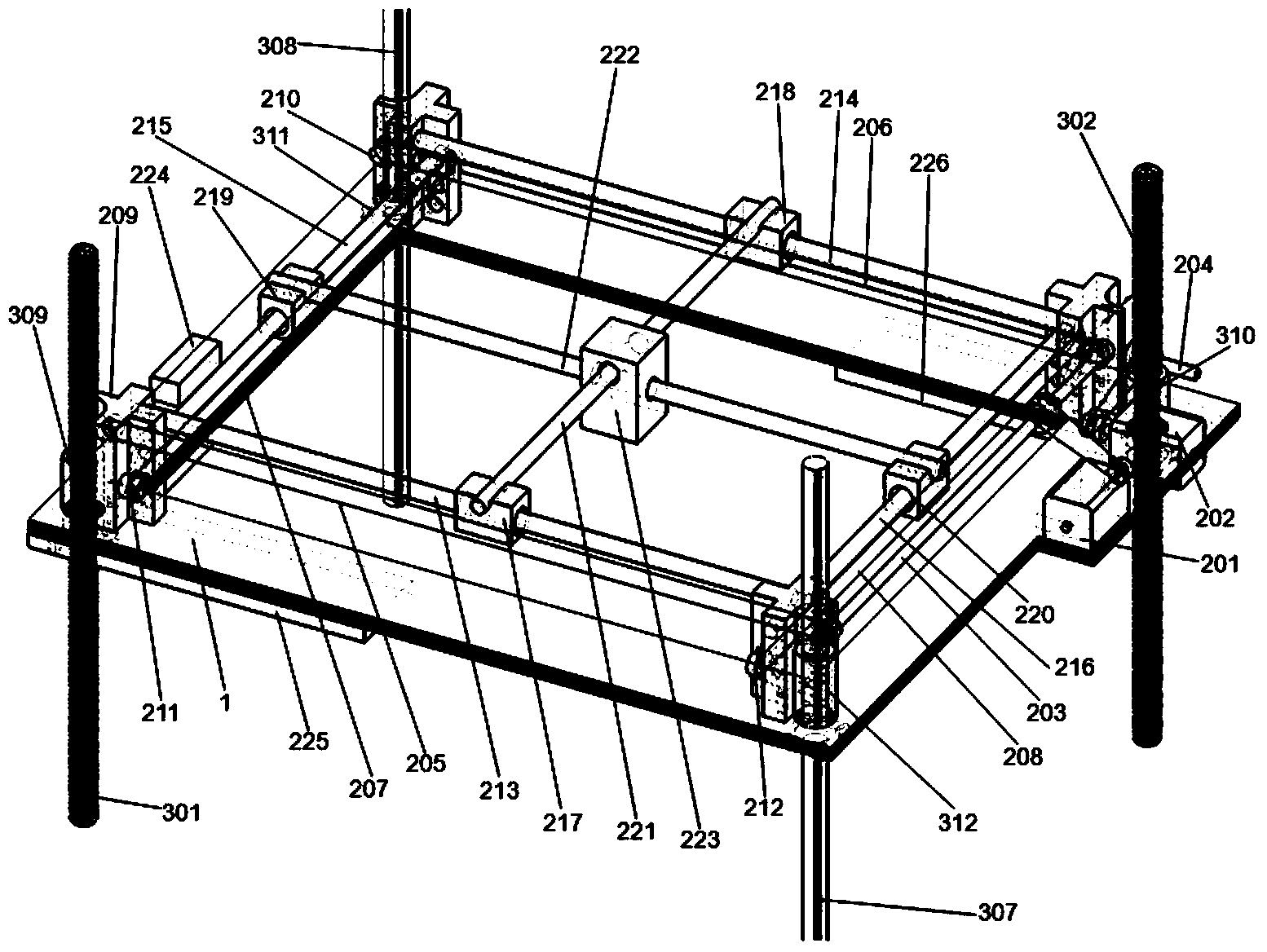
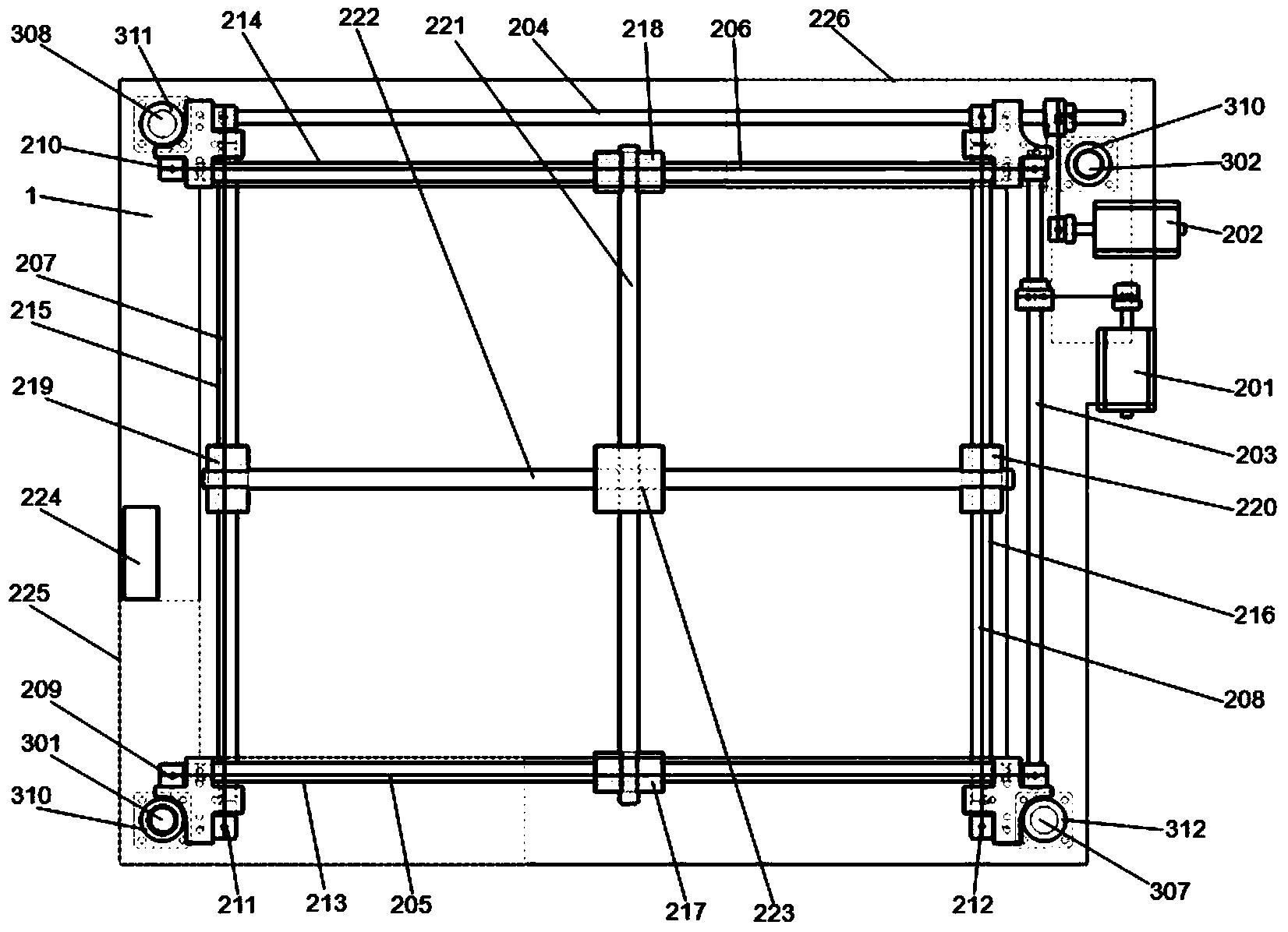
[0027] Such as figure 1 , figure 2 , image 3 As shown, it is a 3D printing system structure of the present invention, which consists of a printing platform 1, a base 2, a stage 3, and an X, Y-axis transmission mechanism located on the printing platform 1, connecting the printing platform 1 and the base 2 Composition of the Z-axis drive mechanism. The X and Y axis transmission mechanisms are independent and will not interfere with each other during work. X transmission mechanism is made up of X driving shaft 203, the first sliding shaft 213, the second sliding shaft 214, the first driven bearing 209, the second driven bearin...


PUM


Abstract

The invention relates to a 3D (three-dimensional) printing system structure. The 3D (three-dimensional) printing system structure comprises a lifting printing platform, a dual-screw dual-optical-axis Z-shaft driving mechanism, an X-shaft drive mechanism, a Y-shaft drive mechanism as well as a stationary object carrying platform, wherein the printing platform is provided with an X-shaft drive motor and a Y-shaft drive motor; the two motors are respectively connected to a pair of driven bearings by synchronous belts at two ends of the driving shaft; double slide shafts in the X direction and the Y direction are both provided with slide seats; two pairs of slide seats are respectively connected by an X cross beam and a Y cross beam, and the two cross beams respectively penetrate through a 3D printer head; a driving motor of the dual-screw dual-optical-axis driving mechanism and the driving shaft are connected by the synchronous belt; the position of the driving motor can be adjusted randomly. The X-shaft drive mechanism, the Y-shaft drive mechanism and the driving shaft operate individually, so that the motion modulation is reduced; the dual-screw dual-optical-axis driving mechanism has favorable stability, so that the printing platform is stressed in a balance manner; the driving in each direction is stable; the 3D printing precision is improved.

Description

technical field [0001] The invention belongs to the technical field of 3D printing, and in particular relates to a 3D printing system structure. Background technique [0002] In the existing small 3D printers, a composite shaft device that provides rotation and sliding at the same time is mostly used to drive the movement of the 3D printer head in the X and Y directions. Since the same shaft is used as a sliding shaft and a rotating shaft at the same time, the device will be affected by various interference factors during operation, thereby affecting the machining accuracy. When the 3D printer head works for a long time, the disadvantages will be more prominent, which greatly reduces the quality or pass rate of the processed parts. [0003] At the same time, most existing small 3D printers use L-shaped unilateral suspension to provide Z-axis movement. This device only uses a vertical screw to drive the stage to move in the Z-axis direction. Due to the unilateral suspension...

Claims


Application Information

Patent Timeline
Patent Type & Authority Applications(China)
IPC IPC(8): B29C67/00
Inventor 吴旭周江宁何海辉何立群刘振邦程新萍孙红娟
Owner UNIV OF SCI & TECH OF CHINA
Why Eureka
Try Eureka