
Horizontal electroplating bath and electroplating zone negative and positive pole gap automatic compensation method

An automatic compensation, electroplating tank technology, applied in the direction of plating tank, electrolysis process, electrolysis components, etc., can solve the problems of blocked electroplating process, no consideration of cold-rolled thin strip, and high energy consumption

Active Publication Date: 2014-06-04
BAOSHAN IRON & STEEL CO LTD
View PDF9 Cites 2 Cited by
  • Summary
  • Abstract
  • Description
  • Claims
  • Application Information

AI Technical Summary

Problems solved by technology

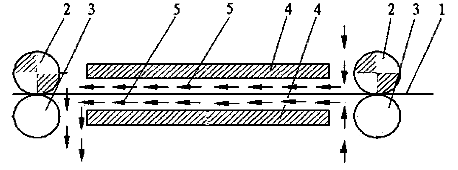
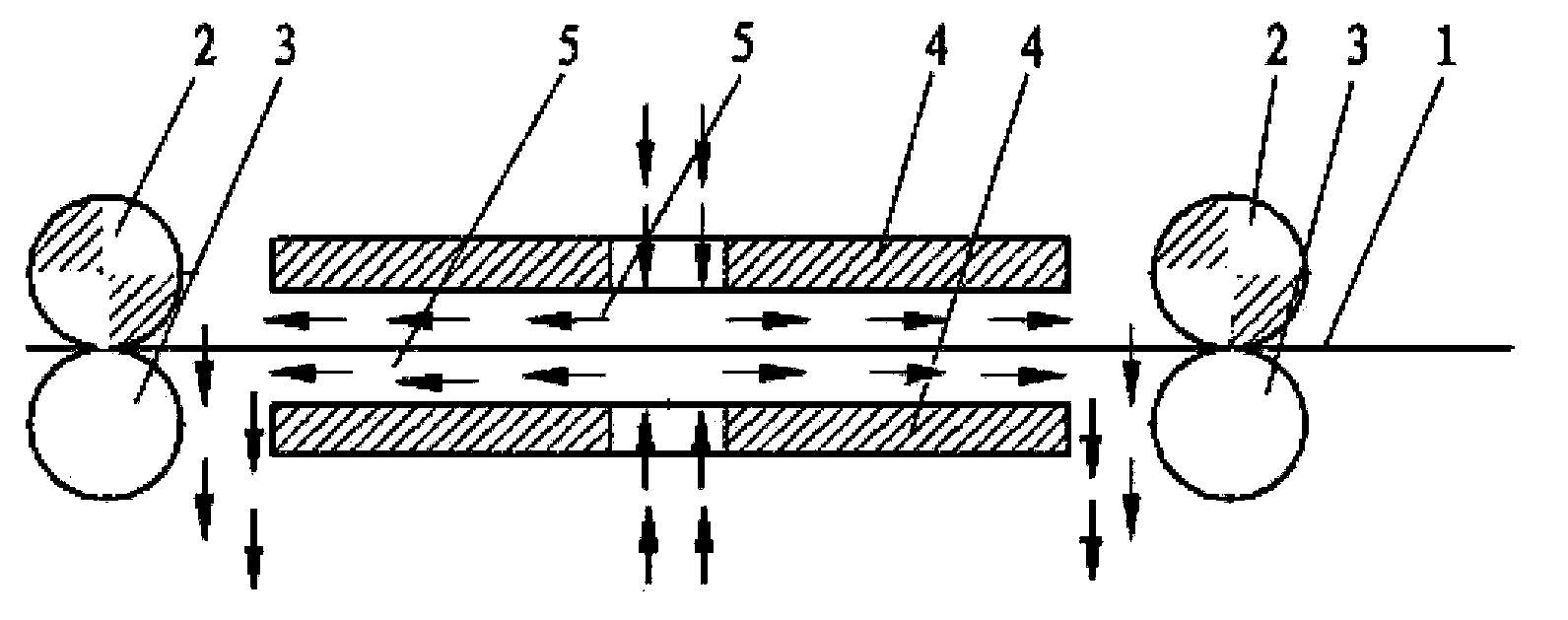
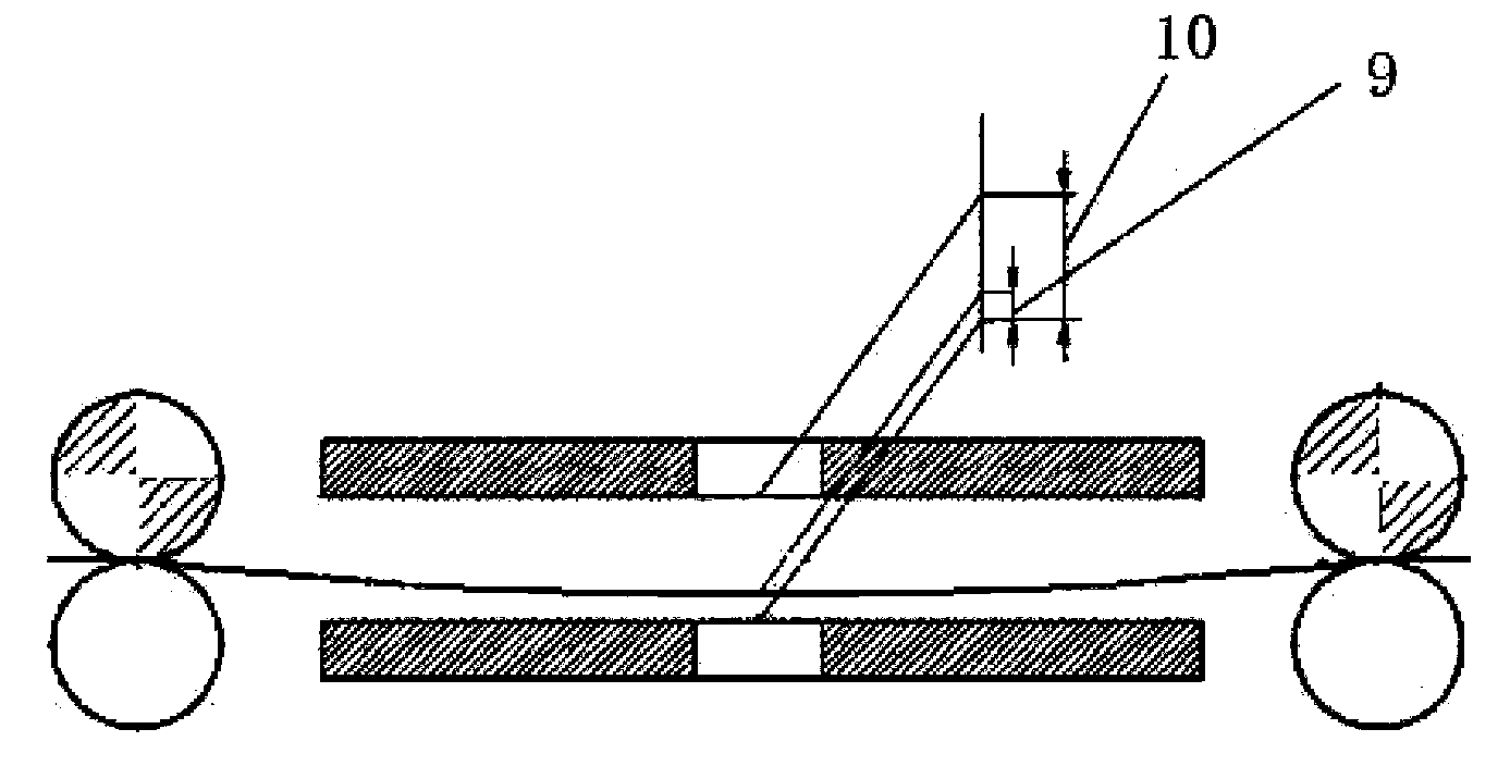
[0007] In summary, the disadvantage of the existing horizontal electroplating tank is that the influence of the sag produced by the cold-rolled thin strip’s self-weight on the distance of the electroplating area is not considered in the design, and there is no corresponding adjustment function, resulting in the cold-rolled thin strip used as the cathode. The distance between the strip steel and the anode plate as the anode will change, and there will be hidden dangers of mechanical abrasion and electrical short circuit
At the same time, the sag produced by the cold-rolled thin strip under the action of its own weight will reduce the electroplating efficiency, increase energy consumption, reduce product quality, and hinder the electroplating process.

Method used


Image

  • Horizontal electroplating bath and electroplating zone negative and positive pole gap automatic compensation method
  • Horizontal electroplating bath and electroplating zone negative and positive pole gap automatic compensation method
  • Horizontal electroplating bath and electroplating zone negative and positive pole gap automatic compensation method

Examples


Embodiment Construction

[0058] The present invention will be further described below in conjunction with the examples, and those skilled in the art should understand that the examples are only for illustration and do not constitute any limitation to the present invention.

[0059] A continuous thin strip steel surface galvanizing production line adopts the technology proposed in this patent. The tank type used in this production line is LCC-H plating tank. The specifications of the strip steel produced are 0.5-2.0mm in thickness and 800-1550mm in width , the maximum speed of the production line is 150m / min, double-sided galvanized. The gap between the lower surface of the cold-rolled thin strip and the lower anode plate is δ, the gap between the upper and lower anode plates is 18mm, the distance between the centerlines of two adjacent conductive rollers is 2600mm, and the unit tension of the strip is 2kgf / cm2. In the actual production of this production line, the fault that the strip steel touches th...


PUM

PropertyMeasurementUnit
thicknessaaaaaaaaaa

Abstract

The invention provides a horizontal electroplating bath including a conductive roller (2), a conductive supporting roller (3) and a positive pole plate (4), the conductive roller (2) is used for transmission of a strip steel (1) and conduction of cathodic current in the electroplating process, the conductive supporting roller (3) is used for compacting the strip steel (1) and the conductive roller (2), the horizontal electroplating bath is characterized by also including a tilting device, the tilting device comprises a pivot (6) located at the positive pole plate end, under the action of a lifting device (7), the positive pole plate (4) can pivot around the pivot (6) to change the relative position of the positive pole plate (4) and the strip steel (1). The invention provides an electroplating zone negative and positive pole gap automatic compensation method of the horizontal electroplating bath, delta automatic compensation can be realized by regulating the tilting device according to gap compensation amount DELTA (delta) = D-delta. The electroplating zone negative and positive pole gap automatic compensation method realizes the real-time compensation of a negative and positive pole gap so as to avoid the direct contact of negative and positive poles, mechanical damages and electrical short circuit and realize smooth running of the electroplating process.

Description

technical field [0001] The invention belongs to the field of cold-rolled thin strip steel production, and in particular relates to a horizontal electroplating tank adopted for surface electroplating of cold-rolled thin strip steel and a method for automatically compensating the cathode and anode gaps in the electroplating area. Background technique [0002] The continuous electroplating line for the surface of cold-rolled strip steel currently used in the industrial field, such as the continuous electrogalvanizing line for the surface of thin strip steel, can be divided into horizontal electroplating tanks and vertical electroplating tanks according to the orientation of the electroplating area. Among them, the horizontal electroplating tank has a compact structure, and the strip passes through the electroplating area horizontally, which is suitable for electroplating of high-strength and thick-spec strip steel. There are typically two types of horizontal plating tanks that ...

Claims


Application Information

Patent Timeline
Patent Type & Authority Applications(China)
IPC IPC(8): C25D17/02C25D21/12C25D7/06
Inventor 唐成龙刘益民李俊黄胜标姚勇
Owner BAOSHAN IRON & STEEL CO LTD
Learn More