Three-direction displacement measurement method based on laser speckle imaging technology

A laser spot, three-direction displacement technology, applied in measurement devices, optical devices, instruments, etc., can solve the problems of large measurement errors, low work efficiency, and inability to realize automatic early warning of online monitoring.

Active Publication Date: 2014-06-04
ZHEJIANG HUADONG SURVEYING MAPPING & GEOINFORMATION
View PDF5 Cites 23 Cited by
  • Summary
  • Abstract
  • Description
  • Claims
  • Application Information

AI Technical Summary

Problems solved by technology

These instruments and equipment have high cost, low work efficiency, low degree of automation, many human influence factors, large measurement errors, and cannot realize online monitoring and automatic early warning.

Method used


Image

  • Three-direction displacement measurement method based on laser speckle imaging technology
  • Three-direction displacement measurement method based on laser speckle imaging technology
  • Three-direction displacement measurement method based on laser speckle imaging technology

Examples


Embodiment Construction

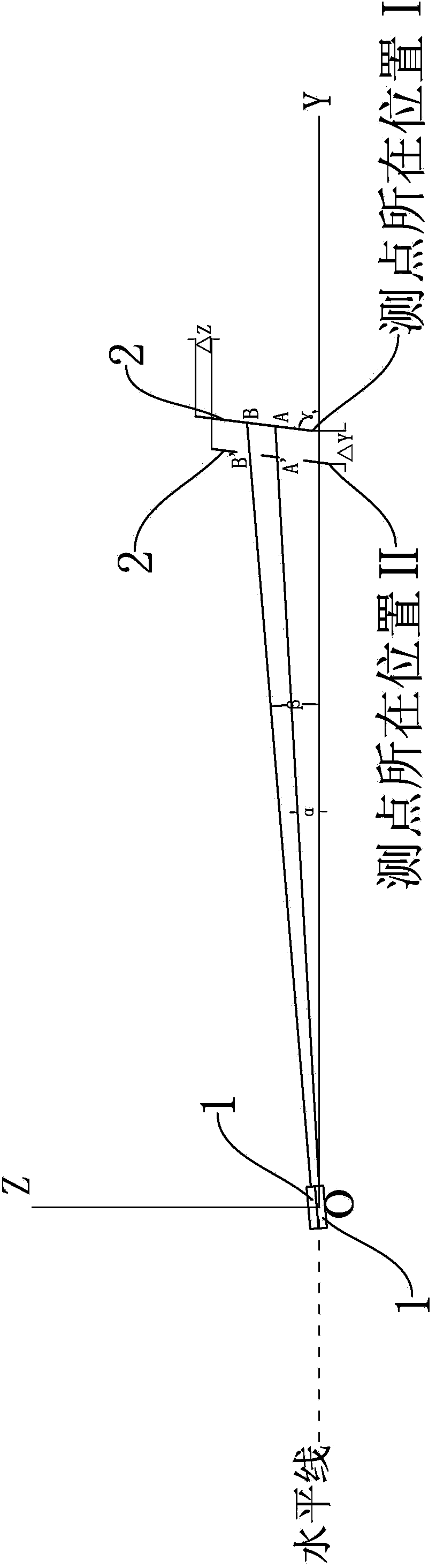
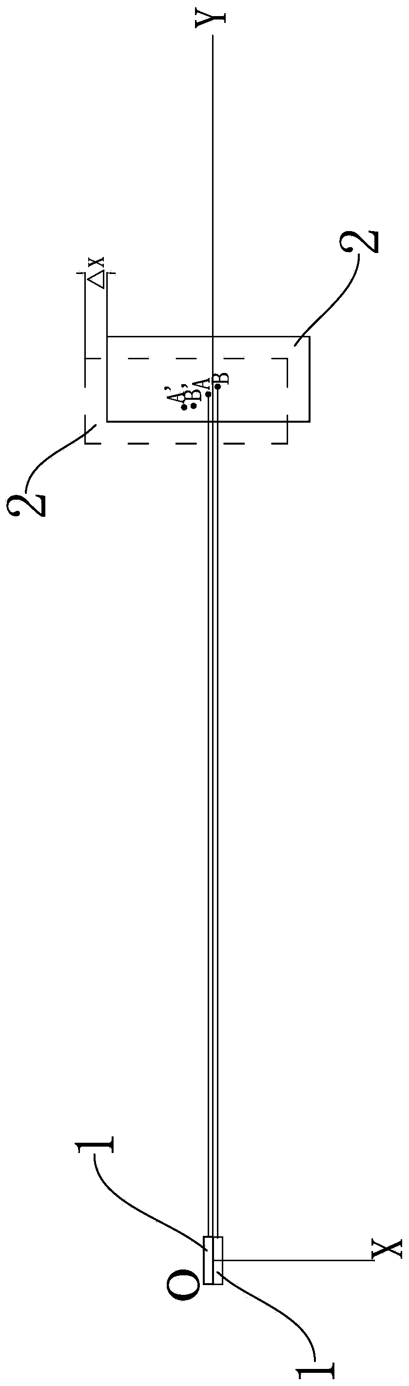
[0042] In this embodiment, two laser beams forming a certain angle are used to image on the imaging target surface 2, and the imaging center of the imaging target surface 2 and the center position changes of the two laser beams are obtained by the laser spot imaging system to calculate the position of the target surface 2. Change, so as to measure the three-way displacement of the laser emitting point and the imaging receiving point.

[0043] Such as figure 1 , figure 2 As shown, this example includes two sets of laser emitters 1 and a laser spot imaging system. The laser spot imaging system includes an imaging target surface 2, an imaging lens, an imaging optoelectronic device (CCD or CMOS photoelectric conversion device) and a signal processing unit.

[0044] The specific implementation steps of this embodiment are as follows:

[0045] 1. Install two sets of laser transmitters 1 at the reference point O, and install the laser spot imaging system at the test point I;

[0...


PUM


Abstract

The invention relates to a three-direction displacement measurement method based on a laser speckle imaging technology. The three-direction displacement measurement method based on the laser speckle imaging technology can achieve synchronous three-direction displacement measurement. According to the technical scheme, the method includes the following steps that firstly, two laser transmitter sets are installed on a reference point, and a laser speckle imaging system is installed on a position I; secondly, light beams are transmitted to an imaging target surface by the laser transmitters and are focused to form a speckle image by an imaging lens, the speckle image is received by an imaging photoelectric device, and the coordinate values of the center points of two speckles relative to the imaging system are found out by a signal processing unit through an image processing algorithm and serve as original values; thirdly, the laser speckle imaging system is moved to a position II, light beams are transmitted to the imaging target surface by the laser transmitters, and the coordinate values of the center points of two speckles relative to the imaging system are found out and serve as test values; fourthly, the test values are compared with the original values, and the horizontal displacement and the vertical displacement are worked out; fifthly, the three-direction displacement of the position II where test points are located relative to the position I is worked out.

Description

technical field [0001] The invention relates to a three-way displacement measurement method, in particular to a three-way displacement measurement method based on laser spot imaging technology. It is suitable for the measurement of one-way, two-way and three-way displacement changes between two test points, as well as the multi-directional displacement change measurement of structural cracks. Background technique [0002] At present, high-precision deformation changes are generally measured by instruments or sensors such as levels, total stations, laser range finders, crack gauges, and electronic levels, and most of them are measured manually. These instruments and equipment have high cost, low work efficiency, low degree of automation, many human influence factors, large measurement errors, and cannot realize online monitoring and automatic early warning. Contents of the invention [0003] The technical problem to be solved by the present invention is to provide a three-...

Claims


Application Information

Patent Timeline
Patent Type & Authority Applications(China)
IPC IPC(8): G01B11/03
Inventor 陈文华王群敏钟聪达卢泳吴勇卢建军
Owner ZHEJIANG HUADONG SURVEYING MAPPING & GEOINFORMATION
Why Eureka
Try Eureka