Pressure sensor chip

A pressure sensor and sensor technology, applied in the direction of measuring fluid pressure, instrument, pressure difference measurement between multiple valves, etc., to achieve the effect of preventing stress concentration, ensuring pressure resistance, and high pressure resistance

Inactive Publication Date: 2014-06-04
YAMATAKE HONEYWELL CO LTD
View PDF5 Cites 10 Cited by
  • Summary
  • Abstract
  • Description
  • Claims
  • Application Information

AI Technical Summary

Problems solved by technology

However, since the pressure sensor chip 1 is protected from excessive pressure Pover by having the recesses 10a, 10b for restricting the displacement of the central diaphragm 6 and the barrier diaphragms 5a, 5b, it cannot be avoided. Enlargement of shape

Method used


Image

  • Pressure sensor chip
  • Pressure sensor chip
  • Pressure sensor chip

Examples


Embodiment Construction

[0044] Hereinafter, embodiments of the present invention will be described in detail based on the drawings.

[0045] [Embodiment 1]

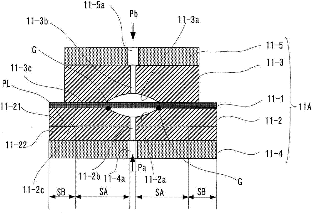
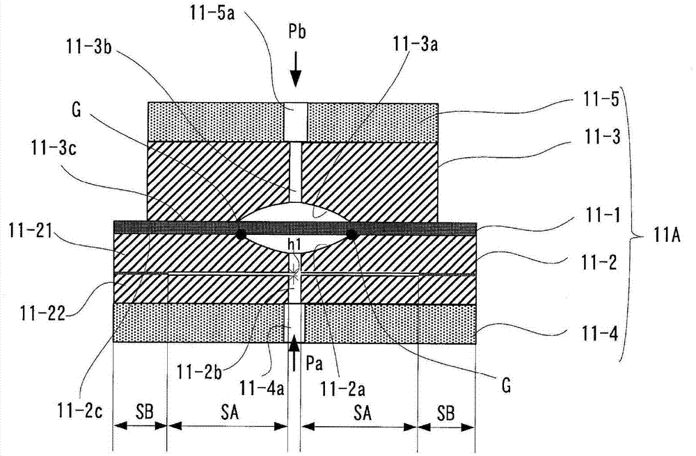
[0046] figure 1 It is a schematic diagram showing the first embodiment (Embodiment 1) of the pressure sensor chip according to the present invention. In this figure, with Figure 12 same notation as with reference to Figure 12 The description of the members that are the same as or equivalent to those described will be omitted. In addition, in this embodiment, the pressure sensor chip is denoted by symbol 11A, and Figure 12 The pressure sensor chip 11 shown in the difference.

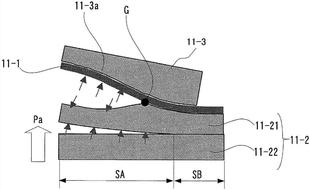
[0047] With this pressure sensor chip 11A, the stopper member 11-2 has a non-joint area SA inside that communicates with the peripheral portion of the pressure guide hole 11-2b. This non-joint area SA is provided on a part of the surface PL parallel to the pressure receiving surface of the sensor diaphragm 11-1. The non-joining area SA is formed by roughening the...


PUM


Abstract

The invention provides a pressure sensor chip reducing stress produced by limitation caused by sensor diaphragm and prevents excessive dislocation of the sensor diaphragm when an excessively large pressure is applied to the sensor diaphragm. A part of face PL that is in a retaining component 11-2 and in parallel with a stress face of the sensor diaphragm (11-1) is communicated with a non-bonding area SA on the periphery of a pressure guiding hole 11-2b. For example, by combining the area of the face of the non-bonding area SA with the non-bonding area SA removed, one part of the retaining component 11-21 and the other part of the retaining component 11-22 that are divided into two parts are combined into a retaining component (11-2). Thus, a face that is parallel with a stress face of the sensor diaphragm (11-1) is divided into the non-bonding area SA communicated to the periphery of the pressure guiding hole (11-2b) and a bonding area (SB) not communicated with the periphery of the pressure guiding hole (11-2b).

Description

technical field [0001] The present invention relates to a pressure sensor chip using a sensor diaphragm that outputs a signal corresponding to the pressure difference received on one surface and the other surface. A pressure sensor chip that detects the pressure applied to the diaphragm by changes in the resistance value of the resistance strain gauge on the diaphragm. Background technique [0002] Conventionally, as a differential pressure sensor for industrial use, a differential pressure sensor incorporating a pressure sensor chip using a sensor diaphragm that outputs a signal corresponding to a pressure difference received on one surface and the other surface is used. In this differential pressure sensor, the measured pressures applied to the pressure-receiving diaphragms on the high-pressure side and the low-pressure side are guided to one surface and the other surface of the sensor diaphragm through the filling liquid as a pressure transmission medium, and the deformat...

Claims


Application Information

Patent Timeline
Patent Type & Authority Applications(China)
IPC IPC(8): G01L9/04
CPCG01L7/082G01L9/0051G01L13/025G01L9/00G01L13/00G01L19/06
Inventor 德田智久濑户祐希
Owner YAMATAKE HONEYWELL CO LTD
Why Eureka
Try Eureka