Pressure Sensor Chip

A pressure sensor and sensor technology, which is applied in the direction of measuring fluid pressure, instruments, pressure difference measurement between multiple valves, etc., to achieve the effects of ensuring pressure resistance, eliminating malfunctions, and preventing concentration

Active Publication Date: 2019-03-22
YAMATAKE HONEYWELL CO LTD
View PDF8 Cites 0 Cited by
  • Summary
  • Abstract
  • Description
  • Claims
  • Application Information

AI Technical Summary

Problems solved by technology

However, since the differential pressure sensor 100 has a structure in which the pressure sensor chip 1 is protected from excessive pressure Pover by the recesses 10a, 10b for restricting the displacement of the central diaphragm 6 and the barrier diaphragms 5a, 5b, its shape cannot be avoided. change

Method used


Image

  • Pressure Sensor Chip
  • Pressure Sensor Chip
  • Pressure Sensor Chip

Examples


Embodiment approach 1

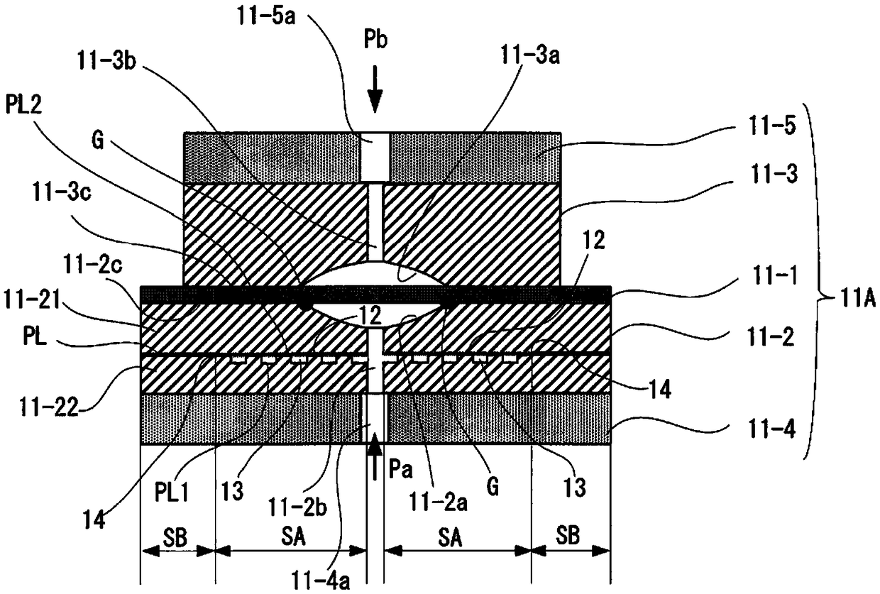
[0054] figure 1 It is a diagram showing the outline of the first embodiment (Embodiment 1) of the pressure sensor chip of the present invention.

[0055] exist figure 1 In the pressure sensor chip 11A shown, 11-1 is a sensor diaphragm, 11-2 and 11-3 are first and second stopper members as holding members bonded via the sensor diaphragm 11-1, 11-4 and 11-5 is the 1st and 2nd pedestal which joins with the stopper member 11-2 and 11-3. The blocking members 11-2, 11-3, and the pedestals 11-4, 11-5 are made of silicon, glass, or the like.

[0056] In this pressure sensor chip 11A, recesses 11-2a, 11-3a are formed in the stopper members 11-2, 11-3, and the recesses 11-2a of the stopper member 11-2 face one side of the sensor diaphragm 11-1. , the concave portion 11-3a of the blocking member 11-3 faces the other face of the sensor diaphragm 11-1. The recesses 11-2a, 11-3a are curved surfaces (aspherical surfaces) along the displacement of the sensor diaphragm 11-1, and pressure...

Embodiment approach 2

[0070] Figure 7 The outline of the second embodiment (Embodiment 2) of the pressure sensor chip of the present invention is shown in . In the pressure sensor chip 11B of the second embodiment, the annular groove 11-2 is formed in the stopper member 11-2 and is continuous with the non-joining area SA and dug in the wall thickness direction of the stopper member 11-3. 2d. As a result, the groove 11-2d is formed so as to protrude in the wall thickness direction of the blocking member 11-3. It is desirable that the ring-shaped groove 11-2d is not a discretely segmented groove but a continuous groove to increase the diameter of the groove section.

[0071] In addition, in Figure 7 In the illustrated example, the cross-sectional shape of the annular groove 11-2d perpendicular to the non-joining area SA is circular, but it may not necessarily be circular, for example, as Figure 8 As shown, it may be slit-shaped (rectangular) or the like.

[0072] Figure 9 In the pressure se...

Embodiment approach 3

[0074] Figure 10 The outline of the third embodiment (Embodiment 3) of the pressure sensor chip of the present invention is shown in . Like the pressure sensor chip 11B of the second embodiment, the pressure sensor chip 11C of the third embodiment includes a non-joining area SA and an annular groove 11-2d continuous with the non-joining area SA inside the barrier member 11-2. , but differs from the pressure sensor chip 11B of Embodiment 2 in the following points.

[0075] In this pressure sensor chip 11C, a region S1 facing one side of the sensor diaphragm 11-1 in the peripheral portion 11-2c of the barrier member 11-2 includes a region S1a on the outer peripheral side and a region S1b on the inner peripheral side. The region S1a on the outer peripheral side is a bonding region to one surface of the sensor diaphragm 11-1, and the region S1b on the inner peripheral side is a non-bonding region to one surface of the sensor diaphragm 11-1.

[0076] In addition, a region S2 fac...


PUM


Abstract

In the pressure sensor chip of the present invention, a non-joint area (SA) communicating with the periphery of the pressure guiding hole (11-2b) is provided inside the blocking member (11-2). On at least one of the opposing first surface (PL1) and second surface (PL2) of the non-joining area (SA), a plurality of convex portions (12) are discretely formed, and the plurality of convex portions (12) The passage (13) between the protrusion (12) serves as a communication path between the peripheral portion of the pressure guide hole (11-2b) and the peripheral end portion (14) of the non-joining area (SA). This prevents stress from concentrating on the edge of the diaphragm and ensures a desired withstand voltage.

Description

technical field [0001] The present invention relates to a pressure sensor chip using a sensor diaphragm that outputs a signal corresponding to the pressure difference received on one side and the other side, for example, involves forming a resistance strain gauge on a sheet-shaped diaphragm that is displaced by pressure and based on the A pressure sensor chip that detects the pressure applied to the diaphragm by changing the resistance value of the resistance strain gauge of the diaphragm. Background technique [0002] Conventionally, as an industrial differential pressure sensor, a differential pressure sensor incorporating a pressure sensor chip using a sensor diaphragm that outputs a signal corresponding to a pressure difference received on one side and the other side has been used. [0003] This differential pressure sensor is configured to transmit the measured pressures applied to the pressure-receiving diaphragms on the high-pressure side and the low-pressure side to ...

Claims


Application Information

Patent Timeline
Patent Type & Authority Patents(China)
IPC IPC(8): G01L19/06G01L13/02
CPCG01L13/02G01L9/0054G01L9/0073G01L19/0618G01L9/0072G01L9/0042G01L19/147G01L19/148
Inventor 德田智久石仓义之
Owner YAMATAKE HONEYWELL CO LTD
Why Eureka
Try Eureka