Method for determining half-wave voltage of phase modulator

A technology of phase modulator and phase voltage, which is applied in the direction of measuring current/voltage, instruments, and measuring electrical variables, etc., and can solve problems such as phase mismatch

Active Publication Date: 2014-06-04
ANHUI QASKY QUANTUM SCI & TECH CO LTD
View PDF8 Cites 2 Cited by
  • Summary
  • Abstract
  • Description
  • Claims
  • Application Information

AI Technical Summary

Problems solved by technology

[0003] Phase modulators are widely used in optical experiments to modulate the phase of photons. However, due to the change of the external environment, the half-wave voltage of the phase modulator is constantly changing, and the phase of the phase modulator at the transmitting end and the receiving end is no longer the same. Matching, interference cannot occur, and the direction of the modulation change of the same type of phase modulator does not necessarily change in the same direction with the increase or decrease of the applied voltage, and may be in the opposite direction. At this time, the 0π and π of the phase modulator at one end The voltage does not need to be changed, but the voltages of π / 2 and 3π / 2 need to be reversed, so a method is needed to accurately calculate the half-wave voltage and judge the direction of modulation change

Method used


Image

  • Method for determining half-wave voltage of phase modulator
  • Method for determining half-wave voltage of phase modulator

Examples


Embodiment 1

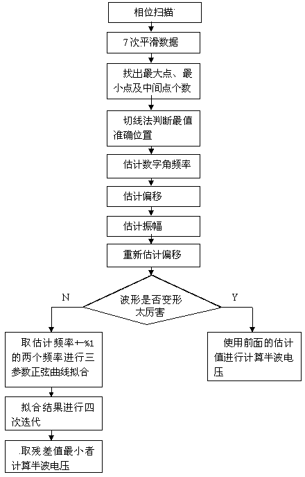
[0022] see figure 1 , the method for determining the half-wave voltage of the phase modulator comprises the following steps:

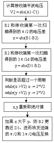
[0023] First, the voltage at the receiving end of the fixed phase modulator is A, and then sweep from the minimum value to the maximum value of the voltage range at the transmitting end of the phase modulator to obtain a sinusoidal curve Q with glitches; as figure 1 As shown, the positions of the maximum point and the minimum point of the transmitting end are obtained by sinusoidal curve fitting, and then the voltages of the four phases of the transmitting end 0π, π / 2, π, and 3π / 2 are calculated; the transmitting end 0π, π / 2 The voltages of the four phases of , π, and 3π / 2 are A, B, C, and D respectively; The half-wave voltage V1 at the end, the mathematical formula for calculation is: the half-wave voltage V1 at the transmitting end is equal to the voltage corresponding to the maximum point minus the voltage corresponding to the minimum point to take...


PUM


Abstract

The invention discloses a method for determining half-wave voltage of a phase modulator. The method comprises the steps that firstly, voltage of a phase position 0pi, voltage of a phase position pi / 2, voltage of a phase position pi, voltage of a phase position 3pi / 2 of an emitting end are calculated; secondly, voltage of a phase position 0pi, voltage of a phase position pi / 2, voltage of a phase position pi, voltage of a phase position 3pi / 2 of a receiving end are calculated; thirdly, the voltage of the phase position pi / 2 is found, the phase voltage of the emitting end of the phase modulator is stabilized to pi / 2, scanning is performed from the minimum value to the maximum value of the voltage range of the receiving end of the phase modulator, a sine curve Q2 is obtained, the corresponding position of the maximum point and the corresponding position of the minimum point of the receiving end are found through fitting, the maximum point corresponds to the voltage of the phase position pi / 2 of the receiving end, and the voltage of the phase position pi / 2 of the receiving end is B2; fourthly, whether the voltage of the phase position pi / 2 and the voltage of the phase position 3pi / 2 of the emitting end are interchanged is determined. According to the method, the half-wave voltage can be accurately calculated when the external environment is changed, and the direction of modulation can be judged. In this way, the phase position of a photon can be accurately modulated so that interference can occur at the two ends.

Description

[0001] technical field [0002] The invention relates to a method for determining the half-wave voltage of a phase modulator by accurately calculating the half-wave voltage and judging the modulation direction when the external environment of the phase modulator changes. Background technique [0003] Phase modulators are widely used in optical experiments to modulate the phase of photons. However, due to the change of the external environment, the half-wave voltage of the phase modulator is constantly changing, and the phase of the phase modulator at the transmitting end and the receiving end is no longer the same. Matching, interference cannot occur, and the direction of the modulation change of the same type of phase modulator does not necessarily change in the same direction with the increase or decrease of the applied voltage, and may be in the opposite direction. At this time, the 0π and π of the phase modulator at one end The voltage does not need to be changed, but th...

Claims


Application Information

Patent Timeline
Patent Type & Authority Applications(China)
IPC IPC(8): G01M11/02G01R19/00
Inventor 佘祥胜苗春华韩正甫赵义博
Owner ANHUI QASKY QUANTUM SCI & TECH CO LTD
Why Eureka
Try Eureka