Transient electromagnetic measurement device and method

A measurement device and transient electromagnetic technology, applied in the field of geophysical exploration, can solve problems such as difficult operation and complicated processing process, and achieve the goal of weakening the influence, improving the signal-to-noise ratio of the secondary field signal, and high-precision transient electromagnetic sounding Effect

Active Publication Date: 2014-06-04
HUNAN WUWEI GEOLOGICAL SCI & TECH CO LTD +1
View PDF4 Cites 38 Cited by
  • Summary
  • Abstract
  • Description
  • Claims
  • Application Information

AI Technical Summary

Problems solved by technology

The optimal matching on the hardware can reduce the induction field of the receiving antenna itself to a certain extent, but the processing process is complicated; the data processing method is feasible in theory, but difficult to operate in practice

Method used


Image

  • Transient electromagnetic measurement device and method
  • Transient electromagnetic measurement device and method
  • Transient electromagnetic measurement device and method

Examples


Embodiment 1

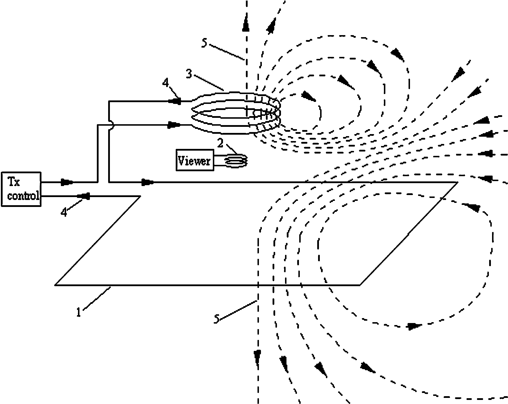
[0025] Embodiment 1: as figure 1 As shown, it is a schematic diagram of a small-frame transmitting device, including a transmitting antenna coil 1, a receiving antenna coil 2, and a zeroing antenna coil 3. The planes of the three are parallel to each other, and the centers of the three are located on the same central axis perpendicular to the plane. . Vertically, the transmitting antenna 1 is closest to the detection area, and the zeroing antenna 3 is above the transmitting antenna 1. The vertical distance of the three antennas is adjustable, but the receiving antenna 2 is guaranteed to be located in the middle of the transmitting antenna 1 and the zeroing antenna 3. The transmitting antenna 1 and the zeroing antenna 3 have the same size, wire type, winding method, and number of turns, and are connected in series in the transmitting loop so that the currents flowing through the two coils are opposite to each other.

[0026] When the transmitter connects current to the transm...

Embodiment 2

[0027] Embodiment 2: as image 3 As shown, it is a schematic diagram of a large-frame transmitting device, including a large-frame transmitting antenna coil 1, a receiving antenna coil 2, and a zero-adjusting antenna coil 3. The receiving antenna 2 is smaller than the zero-adjusting antenna 3, and the zero-adjusting antenna 3 is smaller than the transmitting antenna 1. The planes where the two are located are parallel to each other, and the relative positions in the parallel direction can be adjusted. Vertically, the vertical distance of the three antennas is adjustable (can be on the same plane). The transmitting antenna 1 and the zeroing antenna 3 are connected in series in the transmitting loop, so that the currents flowing through the two coils are opposite to each other. The effective number of turns of the zeroing antenna 3 is adjustable.

[0028] When the transmitter feeds current into the transmitting loop, both the zeroing antenna 3 and the large-frame transmitting ...

Embodiment 3

[0029] Embodiment 3: as Figure 4 As shown, it is a schematic diagram of a dipole device, including a transmitting antenna coil 1, a receiving antenna coil 2, and a zeroing antenna coil 3. The size of the receiving antenna 2 is smaller than that of the zeroing antenna 3 and the transmitting antenna 1. The planes of the three are parallel to each other, and in the parallel direction The relative position on it is adjustable. Vertically, the transmitting antenna 1 is closest to the detection area, the receiving antenna 2 is above the transmitting antenna 1, and the zeroing antenna 3 is above the receiving antenna 2. The horizontal and vertical distances of the three antennas can be adjusted. The zeroing antenna 3 and the transmitting antenna 1 are connected in series in the transmitting loop, so that the current flowing through the two coils flows in the same direction 4 . The effective number of turns of the zeroing antenna 3 is adjustable.

[0030] When the transmitter feeds...


PUM


Abstract

The invention relates to a transient electromagnetic measurement device which comprises a transmitting antenna coil, a receiving antenna coil and a zero setting antenna coil which are parallel to each other. The transmitting antenna coil and the zero setting antenna coil are connected in series. Magnetic flux penetrating through the receiving antenna coil of a primary field generated by the transmitting antenna coil and the zero setting antenna coil is equal to zero or close to zero all the time, the primary field strength of a detection region below a receiving point is ensured, accordingly, the transient process of induction generated by a receiving antenna when emission current is off is eliminated or weakened, the signal to noise ratio of a secondary field signal of an underground medium sensed by the receiving antenna is increased greatly, and high-precision transient electromagnetic detection is achieved.

Description

[0001] technical field [0002] The invention belongs to the field of geophysical exploration, and in particular relates to a transient electromagnetic measuring device and method. Background technique [0003] Transient electromagnetic method is a very important method in the field of geophysical exploration. According to the different system carriers used, it can be divided into aerial transient electromagnetic system, semi-aerial transient electromagnetic system, ground transient electromagnetic system, and well transient electromagnetic system. system, tunnel transient electromagnetic system and water transient electromagnetic system. In this method, a current is passed through the transmitting wire, a primary field is transmitted to the target area, and then the transmitting current is cut off instantaneously, and the secondary eddy current field induced by the medium in the target area is observed with an antenna or a grounding electrode during the switching off interv...

Claims


Application Information

Patent Timeline
Patent Type & Authority Applications(China)
IPC IPC(8): G01V3/10
Inventor 席振铢宋刚周胜黄龙龙霞陈兴朋薛军平张道军侯海涛亓庆新王亮肖炜邓华韦洪兰王鹤
Owner HUNAN WUWEI GEOLOGICAL SCI & TECH CO LTD
Why Eureka
Try Eureka