A transient electromagnetic measuring device and method
A measuring device and transient electromagnetic technology, applied in the field of geophysical exploration, can solve problems such as complicated processing and difficult operation
- Summary
- Abstract
- Description
- Claims
- Application Information
AI Technical Summary
Problems solved by technology
Method used
Image
Examples
Embodiment 1
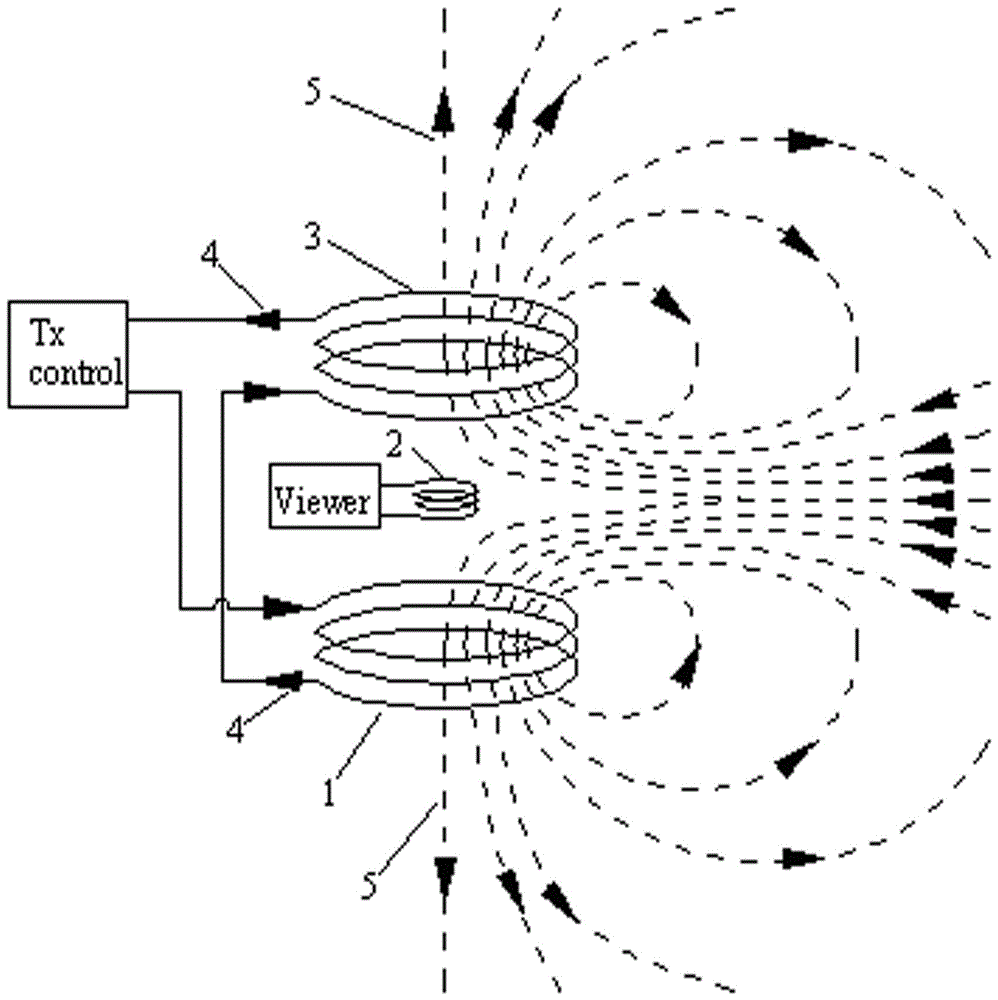
[0024] Embodiment 1: as figure 1 As shown, it is a schematic diagram of a small-frame transmitting device, including a transmitting antenna coil 1, a receiving antenna coil 2, and a zeroing antenna coil 3. The planes of the three are parallel to each other, and the centers of the three are located on the same central axis perpendicular to the plane. . Vertically, the transmitting antenna coil 1 is closest to the detection area, and the zeroing antenna coil 3 is above the transmitting antenna coil 1 . The vertical distance of the three antennas is adjustable, but it is ensured that the receiving antenna coil 2 is located in the middle of the transmitting antenna coil 1 and the zeroing antenna coil 3 . The transmitting antenna coil 1 and the zeroing antenna coil 3 have the same size, wire type, winding method, and number of turns, and are connected in series in the transmitting loop so that the currents flowing through the two coils are opposite to each other.
[0025] When th...
Embodiment 2
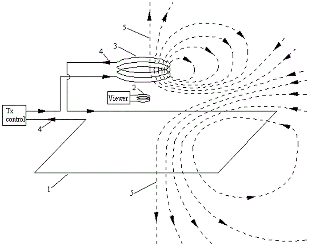
[0026] Embodiment 2: as image 3 As shown, it is a schematic diagram of a large-frame transmitting device, including a large-frame transmitting antenna coil 1, a receiving antenna coil 2, and a zero-adjusting antenna coil 3. The size of the receiving antenna coil 2 is smaller than that of the zero-adjusting antenna coil 3, and the size of the zero-adjusting antenna coil 3 is smaller than that of the transmitting antenna. The planes of the coil 1 and the three are parallel to each other, and their relative positions in the parallel direction can be adjusted. Vertically, the vertical distance of the three antennas is adjustable (can be on the same plane). The transmitting antenna coil 1 and the zeroing antenna coil 3 are connected in series in the transmitting loop, so that the currents flowing through the two coils are opposite to each other. The effective number of turns of the zeroing antenna coil 3 is adjustable.
[0027] When the transmitter feeds current into the transmi...
Embodiment 3
[0028] Embodiment 3: as Figure 4 As shown, it is a schematic diagram of a dipole device, including a transmitting antenna coil 1, a receiving antenna coil 2, and a zeroing antenna coil 3. The size of the receiving antenna coil 2 is smaller than that of the zeroing antenna coil 3 and the transmitting antenna coil 1, and the planes where the three are located are parallel to each other. The relative position in the parallel direction is adjustable. Vertically, the transmitting antenna coil 1 is closest to the detection area, the receiving antenna coil 2 is above the transmitting antenna coil 1, and the zeroing antenna coil 3 is above the receiving antenna coil 2. The horizontal and vertical distances of the three antennas can be adjusted. The zeroing antenna coil 3 and the transmitting antenna coil 1 are connected in series in the transmitting circuit, so that the currents passing through the two coils flow in the same direction 4 . The effective number of turns of the zeroing...
PUM
 Abstract
Description
Claims
Application Information
 - R&D
- Intellectual Property
- Life Sciences
- Materials
- Tech Scout
- Unparalleled Data Quality
- Higher Quality Content
- 60% Fewer Hallucinations
Browse by: Latest US Patents, China's latest patents, Technical Efficacy Thesaurus, Application Domain, Technology Topic, Popular Technical Reports.
© 2025 PatSnap. All rights reserved.Legal|Privacy policy|Modern Slavery Act Transparency Statement|Sitemap|About US| Contact US: help@patsnap.com


