MOM capacitor

A capacitor and electrode technology, applied in the field of semiconductor integrated circuit devices, can solve the problem of small capacitance density

Active Publication Date: 2014-06-04
SHANGHAI HUAHONG GRACE SEMICON MFG CORP
View PDF5 Cites 1 Cited by
  • Summary
  • Abstract
  • Description
  • Claims
  • Application Information

AI Technical Summary

Problems solved by technology

[0002] Capacitors are widely used in radio frequency circuits, such as metal-insulator-metal (MiM) capacitors and MO

Method used


Image

  • MOM capacitor
  • MOM capacitor
  • MOM capacitor

Examples


Embodiment Construction

[0032] Such as Figure 4A As shown, it is a schematic structural diagram of a MOM capacitor according to Embodiment 1 of the present invention; a MOM capacitor according to Embodiment 1 of the present invention: includes a multi-layer metal coil, and each layer of metal coil is formed by nesting two metal sub-coils; Figure 4A shows two adjacent layers of metal coils, namely the upper layer metal coil 1 and the lower layer metal coil 2. The upper metal coil 1 is formed by nesting a first metal sub-coil 11 and a second metal sub-coil 12 . The lower metal coil 2 is formed by nesting a first metal sub-coil 21 and a second metal sub-coil 22 .

[0033] Both the first metal sub-coil 11 and the second metal sub-coil 12 are respectively formed by a metal wire, the winding direction is the same, and the number of turns is also the same. The first metal sub-coil 11 loops clockwise between the outer port 11a and the inner port 11b, and the second metal sub-coil 12 loops clockwise betwe...


PUM


Abstract

The invention discloses an MOM capacitor which is formed by a plurality of layers of metal coils. Each layer of metal coil is formed by nesting two metal sub-coils. The two metal sub-coils of each layer of metal coil form a transverse capacitor structure, that is, the two metal sub-coils form two pole plates of the capacitor; and two metal sub-coils at the upper and lower adjacent two sides are connected together through a through hole. The two pole plates of the MOM capacitor are respectively formed by the metal coils; and since the metal coils have relatively-large parasitic inductance, equivalent capacitance of the MOM capacitor can be improved, capacitance density is increased and circuit area is reduced.

Description

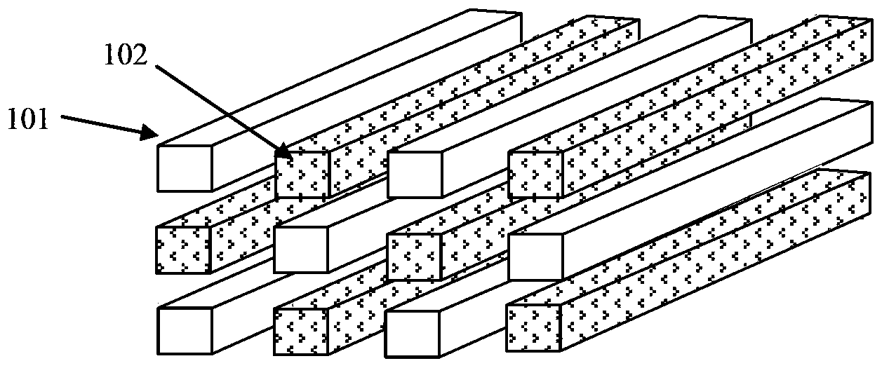
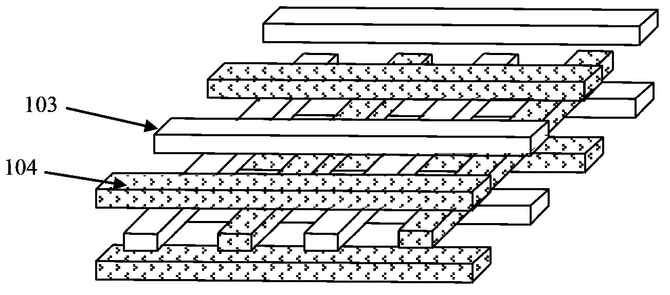
technical field [0001] The invention relates to a semiconductor integrated circuit device, in particular to a metal-oxide-metal (MOM) capacitor. Background technique [0002] Capacitors are widely used in radio frequency circuits, such as metal-insulator-metal (MiM) capacitors and MOM capacitors, but capacitors are often very area-occupied devices, and their capacitance density is relatively small. As the demand for integration becomes higher and higher, the requirement for capacitance density is also higher and higher. [0003] The capacitance density of existing MiM capacitors is generally 2fF / μm 2 Left and right, the existing MOM capacitor structure has three structures. [0004] Such as figure 1 As shown, it is a structural schematic diagram of the first type of MOM capacitor; the first type of MOM capacitor is a horizontal bar structure (Horizontal Barsm, HB), including multiple metal layers, and each metal layer includes metal bars 101 and 102 , the capacitance of ...

Claims


Application Information

Patent Timeline
IPC IPC(8): H01L23/522
Inventor 黄景丰
Owner SHANGHAI HUAHONG GRACE SEMICON MFG CORP
Why Eureka
Try Eureka