Electric power converter

A technology of power converters and capacitors, which is applied in the direction of output power conversion devices, electrical components, circuit devices, etc., and can solve problems such as voltage shocks and shortened extension lengths

Active Publication Date: 2014-06-11
DENSO CORP
View PDF6 Cites 17 Cited by
  • Summary
  • Abstract
  • Description
  • Claims
  • Application Information

AI Technical Summary

Problems solved by technology

[0015] However, there is a problem in the conventional power converter that when the pitch of the stacked bodies is narrowed, the length of the extension portion in the stacking direction may become short
[0022] Therefore, large voltage surges may occur when switching semiconductor elements on and off

Method used


Image

  • Electric power converter
  • Electric power converter
  • Electric power converter

Examples


no. 2 approach

[0179] This embodiment is an example in which the shape of the bus bar 4 and the connection state of the terminal pair 49 are changed.

[0180] Such as Figure 18 As shown, in this embodiment, the terminal pair 49 will adopt any one of the third connection state C or the fourth connection state D.

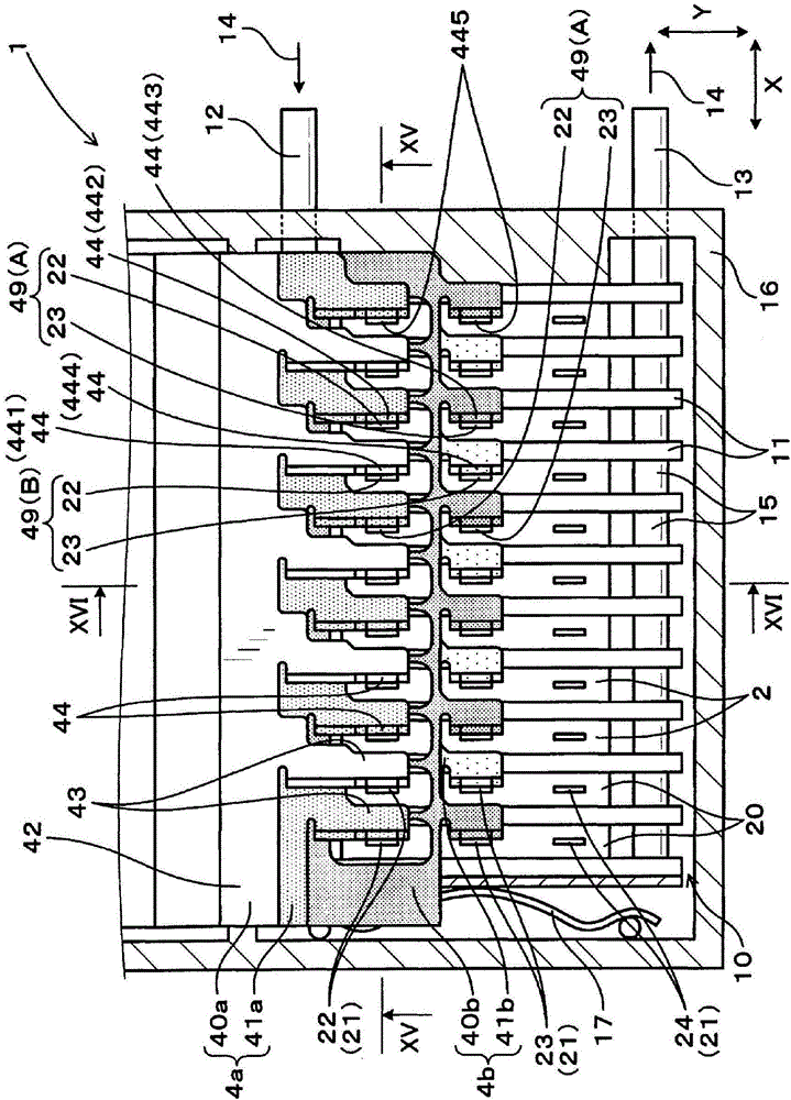
[0181] In the third connection state C, the positive terminal 22 is connected to the terminal connection portion 441 of the distal plate member 40a of the positive bus bar 4a, and the negative terminal 23 is connected to the terminal connection portion 443 of the distal plate member 40b of the negative bus bar 4b.

[0182] In addition, in the fourth connection state D, the positive terminal 22 is connected to the terminal connection portion 442 of the proximal plate member 41a of the positive bus bar 4a, and the negative terminal 23 is connected to the terminal connection portion 444 of the proximal plate member 41b of the negative bus bar 4b .

[0183] Such as Figure 19 As sho...

no. 3 approach

[0191] This embodiment is an example in which the configuration of the capacitor 3 is changed.

[0192] Such as Figure 20 and Figure 21 As shown, the capacitor 3 of the present embodiment has a plurality of capacitor elements 30 ( 30 a , 30 b ) connected in parallel to each other.

[0193] Then, each of the plate members 40, 41 constituting the bus bar 4 is connected to a different capacitor element 30a, 30b, respectively.

[0194] The capacitor element 30 includes a proximal capacitor element 30b disposed at a position closer to the sealing portion 20 in the Z direction and a distal capacitor element 30a disposed at a distance from the sealing portion 20 in the Z direction than the distal capacitor element 30a. The proximal capacitor element 30b is further away.

[0195] The distal plate member 40a of the positive bus bar 4a is connected to the positive electrode 33 of the distal capacitor element 30a, and the proximal plate member 41a is connected to the positive electr...

no. 4 approach

[0212] This embodiment is an example in which the positions of the electrodes of the capacitor elements 30a and 30b are changed.

[0213] In this embodiment, if Figure 22 and Figure 23 As shown, the end surface of the proximal capacitor element 30b closer to the control circuit board 19 in the Z direction and the end surface of the distal capacitor element 30a farther from the control circuit board 19 in the Z direction are configured as positive electrodes 33 .

[0214] Furthermore, the end surface of the proximal capacitor element 30b remote from the control circuit board 19 in the Z direction and the end surface of the distal capacitor element 30a close to the control circuit board 19 in the Z direction are configured as negative electrodes 34 .

[0215] The distal plate member 40a of the positive bus bar 4a is connected to the positive electrode 33 of the distal capacitor element 30a.

[0216] Furthermore, the proximal plate member 41a of the positive bus bar 4a is con...


PUM


Abstract

An electric power converter has a stacked body (10) formed by stacking a plurality of semiconductor modules (2) and coolers (11), a capacitor (3), and positive and negative bus bars (4a, 4b). Each of the bus bars (4a, 4b) is formed by two sheets of plate members (40, 41), respectively. Each of the plate members (40, 41) has a body portion (42), a plurality of extended portions (43), and a plurality of terminal connecting portions (44). The terminal connecting portions (44) are connected to power terminals (21) of the semiconductor modules (2). The main body portion (42) of each plate member (40, 41) are joined to each other so that the terminal connecting portion (44) of the one of the plate members (40) and the terminal connecting portion (44) of the other one of the plate members (41) are disposed alternately in a stacking direction of the stacked body (10).

Description

technical field [0001] The present invention relates to a power converter having a semiconductor module with a built-in semiconductor element, a smoothing capacitor, and a bus bar electrically connected between the semiconductor module and the capacitor. Background technique [0002] Power converters that convert power between AC power and DC power are known. Such a power converter has a stacked body obtained by stacking semiconductor modules having built-in semiconductor elements and coolers for cooling the semiconductor modules (for example, refer to Japanese Patent Application Laid-Open Publication No. 2011-109767). [0003] The semiconductor module has a positive terminal and a negative terminal to which a DC voltage of a DC power source is applied, and an AC terminal connected to an AC load. [0004] Also, power converters have capacitors that smooth the DC voltage. [0005] A plurality of positive terminals are arranged in a row along the stacking direction of the st...

Claims


Application Information

Patent Timeline
Patent Type & Authority Applications(China)
IPC IPC(8): H02M7/00
CPCH05K1/0213H05K7/20927H02M7/003H05K7/14329H05K7/1432
Inventor 冈村诚
Owner DENSO CORP
Why Eureka
Try Eureka