
Resonant converting device

A technology of resonant conversion and resonant converter, which is applied in the direction of output power conversion device, conversion of DC power input to DC power output, adjustment of electrical variables, etc., and can solve problems such as difficult to achieve control effect

Active Publication Date: 2014-06-04
FSP POWERLAND TECH
View PDF8 Cites 13 Cited by
  • Summary
  • Abstract
  • Description
  • Claims
  • Application Information

AI Technical Summary

Problems solved by technology

[0003] When the input voltage Vin contains relatively simple ripples, it is sufficient to increase the gain of the resonant conversion device at this ripple frequency. However, when the input voltage Vin contains harmonic components of various frequencies, the resonant conversion device is required to operate in a wide range. The gain in the frequency range must be very high, and it is difficult to achieve good control effect, especially the ripple suppression effect, only by using the feedback closed-loop design of the resonant converter

Method used


Image

  • Resonant converting device
  • Resonant converting device
  • Resonant converting device

Examples


Embodiment Construction

[0024] The present invention will now be described in detail with reference to exemplary embodiments shown in the accompanying drawings. In addition, wherever possible, components / members using the same reference numerals in the drawings and the detailed description represent the same or similar parts.

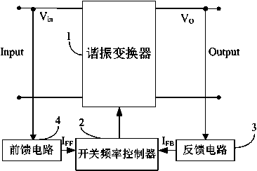
[0025] see figure 2 , shown in the figure is a structural diagram for implementing the present invention, wherein the resonant conversion device has a resonant converter 1, a switching frequency controller 2, and a feedback circuit 3. In order to suppress the ripple of the input voltage, the present invention adds a Feedforward circuit 4, the feedforward circuit 4 is connected to the input end of the resonant converter, samples the input voltage Vin, and converts it into a current signal I FF , the switching frequency controller 2 accepts the current signal I FF And control the switching frequency of the main power switching tube in the resonant converter 1, so that the dir...


PUM


Abstract

The invention discloses a resonant converting device. A feedforward circuit is added into the device. The feedforward comprises a voltage sampling module and a voltage-current conversion module. The voltage sampling module samples a ripple of an input voltage of a resonant converter and provides a sampled value for the voltage-current conversion module, which converts the sampled value into a current signal. The ripple of the input voltage of the device is sampled and converted into the current signal representing a control signal for controlling switch frequency, and the current signal is fed forward to a switch frequency controller for controlling the direction of change of an output gain to be opposite to the direction of fluctuation of the input voltage, so that the device can filter the ripple, an output voltage is not affected by the ripple of the input voltage, and the ripple is relatively small.

Description

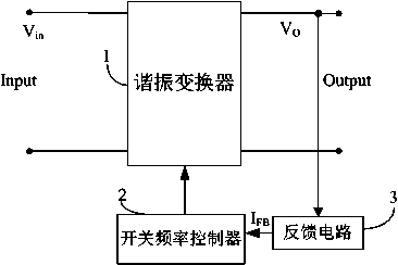
technical field [0001] The invention relates to a power supply device, in particular to a resonant conversion device. Background technique [0002] see figure 1 , which is a structural diagram of a resonant conversion device in the prior art. The device includes a resonant converter 1 having an input terminal input for receiving an input voltage Vin and an output terminal output for providing an output voltage Vo. The switching frequency controller 2 controls the switching frequency of the main power switching tube in the resonant converter 1, and the feedback circuit 3 samples the output voltage and feeds it back to the switching frequency controller 2 to control the switching frequency of the main power switching tube of the resonant converter 1 , so that it outputs a stable output voltage Vo. [0003] When the input voltage Vin contains relatively simple ripples, it is sufficient to increase the gain of the resonant conversion device at this ripple frequency. However, ...

Claims


Application Information

Patent Timeline
IPC IPC(8): H02M1/14H02M3/335
CPCY02B70/10
Inventor 孙巨禄左全平徐明
Owner FSP POWERLAND TECH
Learn More