Programmable controller having a heatsink

A technology of programming controllers and heat sinks, applied in logic controllers for automation/industrial process control, circuit heating devices, modification through conduction heat transfer, etc., can solve problems such as increased power loss, and achieve small structural size , multi-power loss, and the effect of reducing the cost of installation devices and additional tools

Inactive Publication Date: 2014-06-04
SIEMENS AG
View PDF3 Cites 3 Cited by
  • Summary
  • Abstract
  • Description
  • Claims
  • Application Information

AI Technical Summary

Problems solved by technology

The microprocessors used are more and more efficient, so the power consumption goes up

Method used


Image

  • Programmable controller having a heatsink
  • Programmable controller having a heatsink
  • Programmable controller having a heatsink

Examples


Embodiment Construction

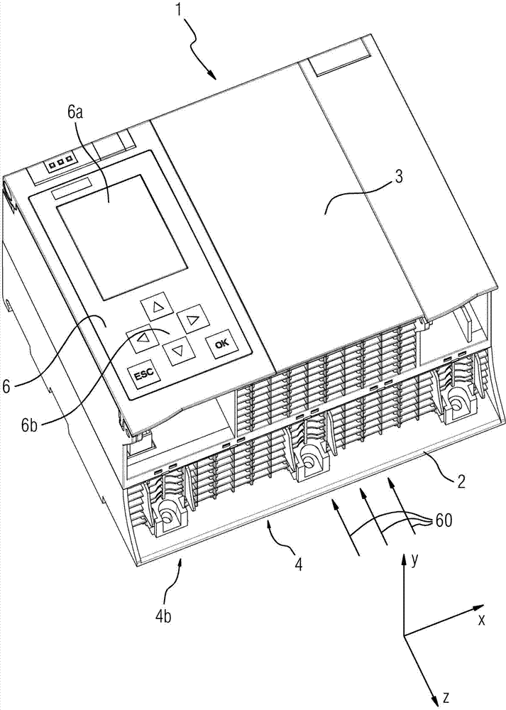
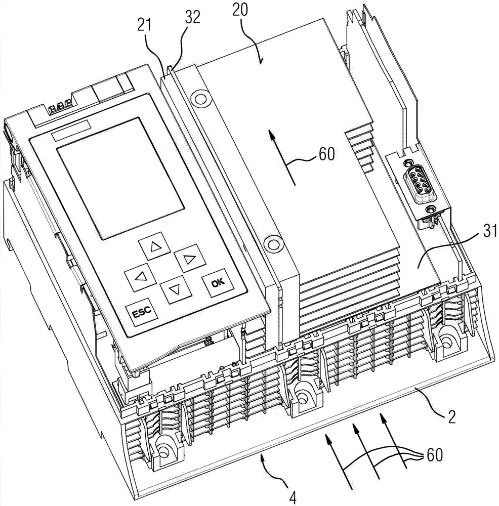
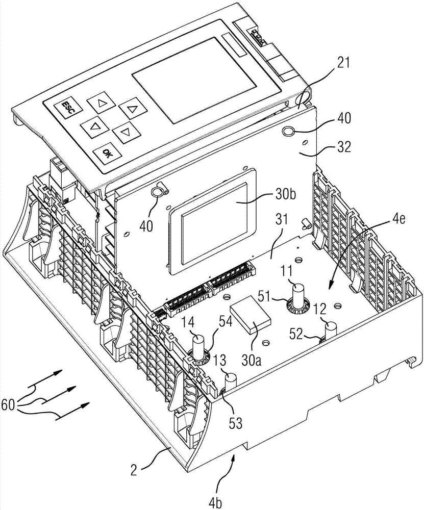
[0023] according to figure 1 Consists of a programmable controller for industrial process automation designed for use in applications in the field of automation. Since programmable controllers are exposed to harsh environmental conditions, such as humidity, temperature differences, vibration loads and shock loads, this programmable controller must be designed to be particularly robust. The shown programmable controller 1 has a base housing 2 and a front cover 3 , wherein a front cover 6 with an integrated display 6 a and an integrated operating panel is additionally shown.

[0024] Three spatial axes x, y, z are shown below the programmable controller 1 . The programmable controller 1 and in particular the internal structure of the programmable controller 1 are displaced on the spatial axes x, y, z in the event of shock loads, vibration loads or vibration loads. in from figure 1 A ventilation grille can be seen in the perspective view of the programmable controller 1 , whic...


PUM


Abstract

The invention refers to an automation device (1) configured for an automation environment and for automating an industrial process, including a first printed circuit board (31), a second printed circuit board (32), a first electronic component (30a) arranged on the first printed circuit board (31) and a second electronic component (30b) arranged on the second printed circuit board (32), a heatsink (20) arranged on the first printed circuit board (31), wherein the first electronic component (30a) is arranged between the first printed circuit board (31) and the heatsink (20), the heatsink (20) has a cuboid shape and rests on the first electronic component (30a) with a first cooling contact surface (24a) incorporated in a first lateral surface (22) of the cuboid and a second cooling contact surface (24b) incorporated in a second lateral surface (23) of the heatsink rests on the second electronic component (30b), and the second printed circuit board (32) is arranged essentially vertically with respect to the first printed circuit board (31).

Description

technical field [0001] The invention relates to a programmable controller designed for use in the field of automation for industrial process automation, which has a first printed circuit board, a second printed circuit board, a first electronic component to be cooled and a second Electronic components to be cooled, the first electronic component to be cooled is arranged on a first printed circuit board and the second electronic component to be cooled is arranged on a second printed circuit board, wherein the heat sink is arranged on the first printed circuit board and The first electronic component is arranged between the first printed circuit board and the heat sink, and the heat sink is also square in design and rests on the first electronic component together with the first heat dissipation contact surface included in the first side of the heat sink. Background technique [0002] Due to the miniaturization of electronic components, higher packing densities / functional dens...

Claims


Application Information

Patent Timeline
Patent Type & Authority Applications(China)
IPC IPC(8): H05K7/20
CPCH05K1/0203H05K7/2039H05K7/20127H05K7/1464H05K7/20154
Inventor 马蒂亚斯·博梅尔尤利娅·米希尔于尔根·施梅尔策
Owner SIEMENS AG
Why Eureka
Try Eureka