Powder mixing device

A mixing device and powder technology, applied in the direction of mixers, dissolution, chemical instruments and methods, etc., can solve the problems of uneven mixing of raw materials, long stirring time, etc., achieve short stirring time, prolong service life, and uniform mixing Effect

Active Publication Date: 2014-06-11
江苏宏创精密制造有限公司
5 Cites 2 Cited by

AI-Extracted Technical Summary

Problems solved by technology

In the actual use process, the stirring time is longe...

Abstract

The invention discloses a powder mixing device which is capable of shortening the stirring time and mixing raw materials evenly. The powder mixing device comprises a support seat, and a closed mixing barrel and a rolling seat which are movably arranged on the support seat, wherein the support seat is provided with a pair of support arms; a rolling shaft passes through the support arms; a rolling gear is arranged on the rolling shaft; the rolling seat is internally provided with a circular arc-shaped roller way matched with the rolling shaft, and a rolling groove matched with the rolling gear; the rolling shaft is restrained in the circular arc-shaped roller way; the rolling seat is internally provided with a driving gear meshed with the rolling gear; the axis line of the driving gear is coincided with that of the circular arc-shaped roller way; the closed mixing barrel is internally provided with a stirring shaft along the axis lines of rotating shafts; the stirring shaft is provided with a spiral stirring blade; the two ends of the stirring shaft are respectively connected with the rotating shaft at the corresponding side. The powder mixing device is especially suitable for mixing of various powder metallurgy materials.

Application Domain

Technology Topic

Image

  • Powder mixing device
  • Powder mixing device

Examples

  • Experimental program(1)

Example Embodiment

[0013] Specific embodiments of the present invention will be described in detail below in conjunction with the accompanying drawings.
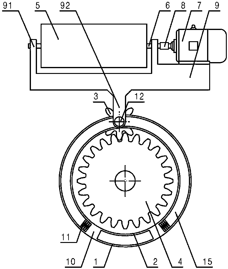
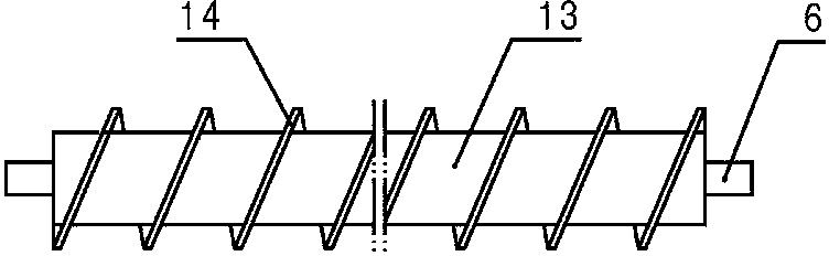
[0014] like figure 1 As shown, a powder mixing device according to the present invention includes: a support 9, an airtight mixing cylinder 5, and a rolling seat formed by a concentric inner cylinder 2 and an outer cylinder 1, and the two ends of the airtight mixing cylinder 5 are respectively A rotating shaft 6 is provided, and a pair of lugs 91 are provided on the support 9, and the pair of rotating shafts 6 are respectively arranged on the corresponding side of the support through bearings (conventional technology, not shown in the figure). On the ear 91, the support 9 is also provided with a geared motor 7 as a power device on one side of the closed mixing tube 5, and the output shaft of the geared motor 7 is connected to the corresponding side of the closed mixing tube 5 through a coupling 8. A pair of support arms 92 are provided on the side of the support 9 facing away from the airtight mixing cylinder 5. The pair of support arms 92 are pierced with a rolling shaft 12, and a rolling shaft 12 is provided on the rolling shaft 12. For the gear 3, the rolling seat is provided with an arc-shaped roller table 15 matched with the rolling shaft 12 and a rolling groove matched with the rolling gear 3 (belonging to conventional technology, not shown in the figure), and the rolling shaft 12 is bound in the arc-shaped roller table 15, the driving gear 4 meshing with the rolling gear 3 is arranged in the rolling seat, the axis line of the drive gear 4 coincides with the axis line of the arc-shaped roller table 15, and the A stirring shaft 13 is also arranged along the axis of the rotating shaft 6 in the closed mixing cylinder 5, as figure 2 As shown, the stirring shaft 13 is provided with a spiral stirring blade 14, and the two ends of the stirring shaft 13 are respectively connected with the rotating shaft 6 on the corresponding side; in this embodiment, the arc-shaped roller table 15 is symmetrical on both sides A pair of limit seats 10 are provided, and a spring hole is provided on the upper end surface of the limit seat 10, and a buffer spring 11 is arranged in the spring hole, and the buffer spring 11 extends out of the limit seat 10 in a free state.
[0015] During practical application, the drive gear 4 is driven by another geared motor. When in use, the geared motor is transmitted to the rolling gear 3 through its output shaft and the drive gear 4, and the support 9 is lifted to the highest point of the arc-shaped roller table 15, and then the support 9 is allowed to carry the closed mixing tube 5 Sliding down freely to the left or right, during the sliding process of the airtight mixing cylinder 5, the raw material moves downward under the action of gravity, at the same time, through the positive and negative rotation of the gear motor 7, the forward or reverse rotation of the stirring shaft 13 Turn, let the helical stirring blade 14 push up against the moving direction of the raw material, so that the raw material is rolled in the closed mixing barrel 5.
[0016] The above embodiments do not limit the present invention in any way, and all technical solutions obtained by means of equivalent replacement or equivalent transformation fall within the protection scope of the present invention.

PUM

no PUM

Description & Claims & Application Information

We can also present the details of the Description, Claims and Application information to help users get a comprehensive understanding of the technical details of the patent, such as background art, summary of invention, brief description of drawings, description of embodiments, and other original content. On the other hand, users can also determine the specific scope of protection of the technology through the list of claims; as well as understand the changes in the life cycle of the technology with the presentation of the patent timeline. Login to view more.

Similar technology patents

Sludge consolidating agent

Owner:大庆油田建设设计研究院

Classification and recommendation of technical efficacy words

  • Well mixed
  • Short mixing time

Method for preparing organic carboxylate from olefin through hydroesterification

InactiveCN102531890ASpecial solubilityWell mixedOrganic-compounds/hydrides/coordination-complexes catalystsPreparation by carbon monoxide or formate reactionCarboxylateCorrosion
Owner:LANZHOU INST OF CHEM PHYSICS CHINESE ACAD OF SCI

Process for the manufacture of (poly-)isocyanates in the gas phase

ActiveUS6974880B2High yieldShort mixing timeIsocyanic acid derivatives preparationLiquid-gas reaction as foam/aerosol/bubblesDiamineIsocyanate
Owner:COVESTRO DEUTSCHLAND AG

Sand mixing and stirring cage of precoated sand mixing machine

InactiveCN104646618AShort mixing timeReduce lossesMould handling/dressing devicesEngineeringMixing tank
Owner:WUXI KANGHUI MACHINE BUILDING
Why Eureka
Try Eureka