Tube bundle reactor

A tube-bundle reactor and reaction technology, applied in chemical instruments and methods, organic chemistry, chemical/physical processes, etc., can solve problems such as side reactions

Active Publication Date: 2014-06-11
MAN ENERGY SOLUTIONS SA
View PDF7 Cites 4 Cited by
  • Summary
  • Abstract
  • Description
  • Claims
  • Application Information

AI Technical Summary

Problems solved by technology

[0003] Within the scope of the present application, the term "dead space" is understood to mean the section of the gas outflow chamber which lies next to the flow path which would be occupied by the reaction gas flowing

Method used


Image

  • Tube bundle reactor
  • Tube bundle reactor
  • Tube bundle reactor

Examples


Embodiment Construction

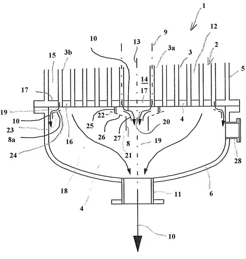
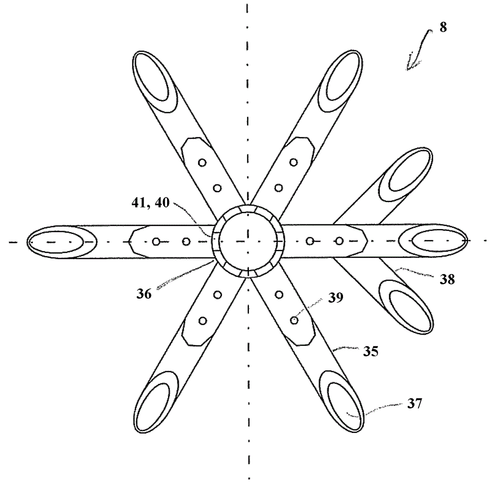
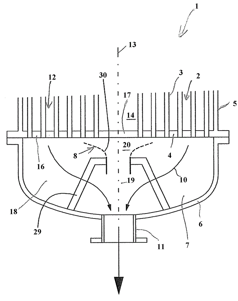
[0025] The illustrated embodiment of the tube bundle reactor 1 according to the invention has a reactor tube 3 bundle 2, a (not shown) gas inflow-side and gas outflow-side tube bottom 4, a reactor shell 5, ( (not shown) gas inflow-side and gas outflow-side reactor housing 6 and gas outflow chamber 7 with flow guiding device 8 .

[0026] The reaction tube 3 runs vertically and is represented by its tube axis 9 . For reasons of clarity only twelve reaction tubes 3 are shown. The actual number of reaction tubes 3 is much larger and may exceed 30,000.

[0027] During reactor operation, the reaction tubes 3 are filled with catalyst material and flowed through by a reaction gas 10 . In the illustrated embodiment, the reaction gas 10 flows from top to bottom.

[0028] The reaction tube 3 is welded with its ends in a sealing manner in a through-opening in the tube base 4 and leads into a (not shown) gas inflow chamber or into a gas outflow chamber 7 . In the illustrated embodiment...


PUM


Abstract

The present invention relates to a tube bundle reactor, which is used for executing a catalyzed gas phase reaction. The tube bundle reactor is provided with a reaction buddle (filled with catalyst in operation and for the reaction gas to flow), tube bottoms at gas inlet side and gas outlet side, and a reactor shell (surrounding the tube bundle and connected with tube bottoms in a sealing manner so as to build a shell chamber in which reaction pipes are washed by heat carriers in operation), wherein the tube bottom of the gas outlet side is provided with at least a tube bottom section which is taken by the tube buddle and at least a second tube bottom section with no tube buddle; a gas outlet chamber is provided with at least a first gas outlet chamber section (aligned with the fist tube bottom section), at least a second gas outlet chamber section (aligned with a second tube bottom section and provided with a dead chamber), and at least a flow guiding device which is disposed in the second gas outlet chamber section and which is constructed so that part of the reaction gas flowing out from the reaction tube is guided to the dead chamber from the first gas outlet chamber section.

Description

technical field [0001] The invention relates to a tube bundle reactor according to the preamble of claim 1 . Background technique [0002] Such tube bundle reactors are known, for example, from documents US 7,554,836 B2 and WO 2008 / 009466 A1. In these documents it is proposed to arrange the extrusion body in a section of the gas outflow chamber that is aligned with the tube-free or tube-bundle-free region in the shell chamber. The squeeze body prevents the reaction gas flowing out of the reaction tube from flowing there into a dead space of the gas outflow chamber next to the main flow of reaction gas. [0003] Within the scope of the present application, the term "dead space" is understood to mean the section of the gas outflow chamber which lies next to the flow path which would be occupied by the reaction gas flowing out of the reaction tube without flow guides, and in which dead space In that case there are undefined flow conditions and the reaction gas therefore stays...

Claims


Application Information

Patent Timeline
IPC IPC(8): B01J8/06
CPCB01J8/06C07C47/22C07C57/04B01J8/008B01J8/067B01J2208/00849B01J2208/00938B01J2219/00245
Inventor M.莱尔A.戈尔德曼W.舒斯特
Owner MAN ENERGY SOLUTIONS SA
Why Eureka
Try Eureka