Extrusion mold with improved structure

An extrusion die and structure improvement technology, applied in the direction of metal extrusion dies, etc., can solve the problems of difficult forming, rough product surface, unfavorable material forming, etc., and achieve the effect of good forming effect, high overall strength and not easy to damage

Inactive Publication Date: 2014-06-11
捷安特轻合金科技(昆山)股份有限公司
View PDF10 Cites 3 Cited by
  • Summary
  • Abstract
  • Description
  • Claims
  • Application Information

AI Technical Summary

Problems solved by technology

[0002] All kinds of profiles are formed by extrusion dies. Generally, extrusion dies are composed of an upper die and a lower die. The upper die is equipped with a deflector and a core head. The material flows through the diversion holes on the deflector and then enters the mold. Then it flows into the welding chamber, and after entering the welding chamber, it gathers the flow, and then enters the molding space formed by the core head and the forming hole for extrusion molding, and finally discharges from the discharge hole. At present, the common shunt hole is a straight hole , the material is not easy to enter, the shunting effect is not good, and the welding chamber is a one-layer structure, the material is directly entered into the forming hole for forming after a converging flow, which is not conducive to material forming, and the internal structure of the formed material is loose, which affects the product. The molding speed and molding quality are poor, resulting in rough product surface, difficult molding, and low strength of molded products.

Method used


Image

  • Extrusion mold with improved structure
  • Extrusion mold with improved structure
  • Extrusion mold with improved structure

Examples


Embodiment

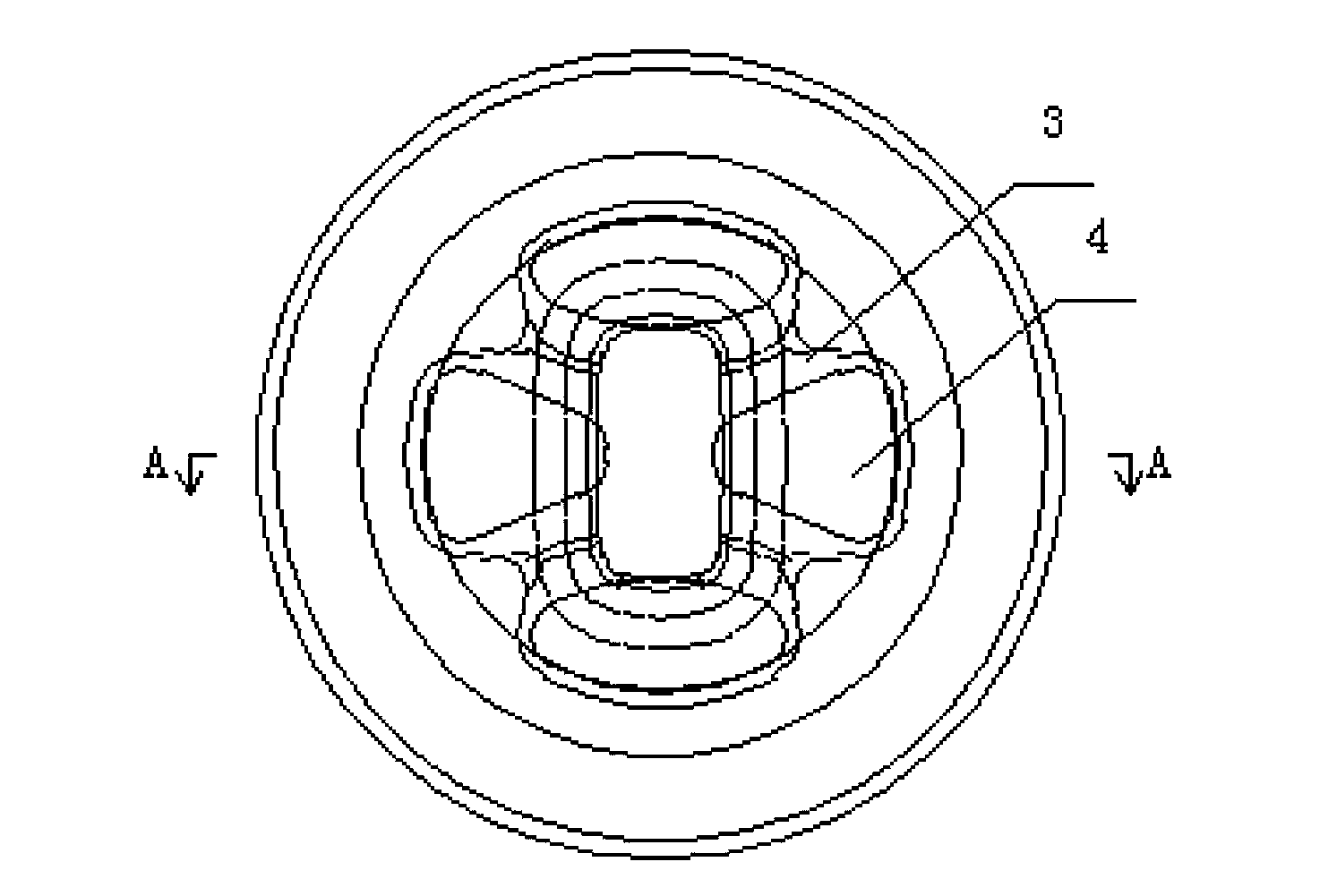
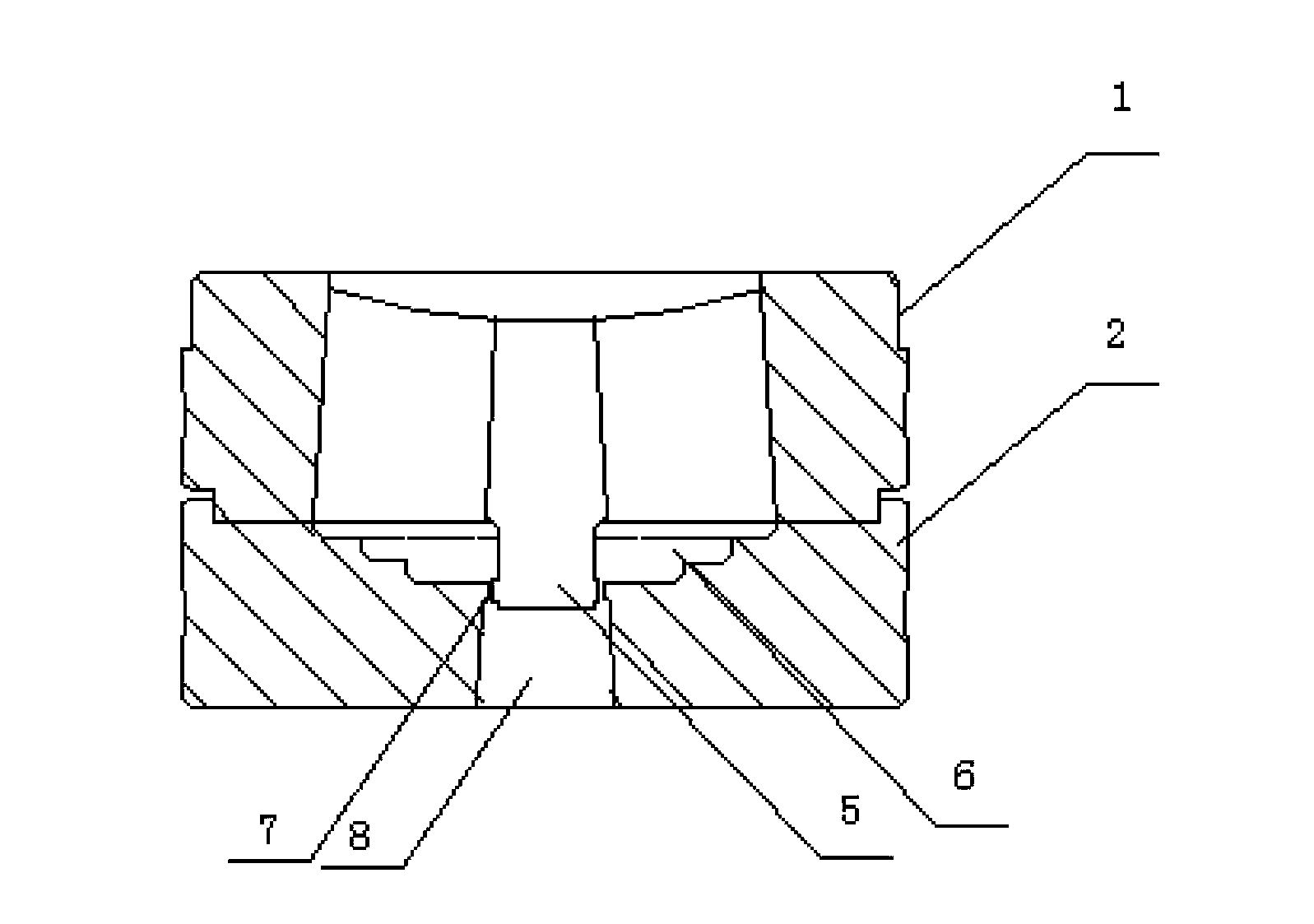
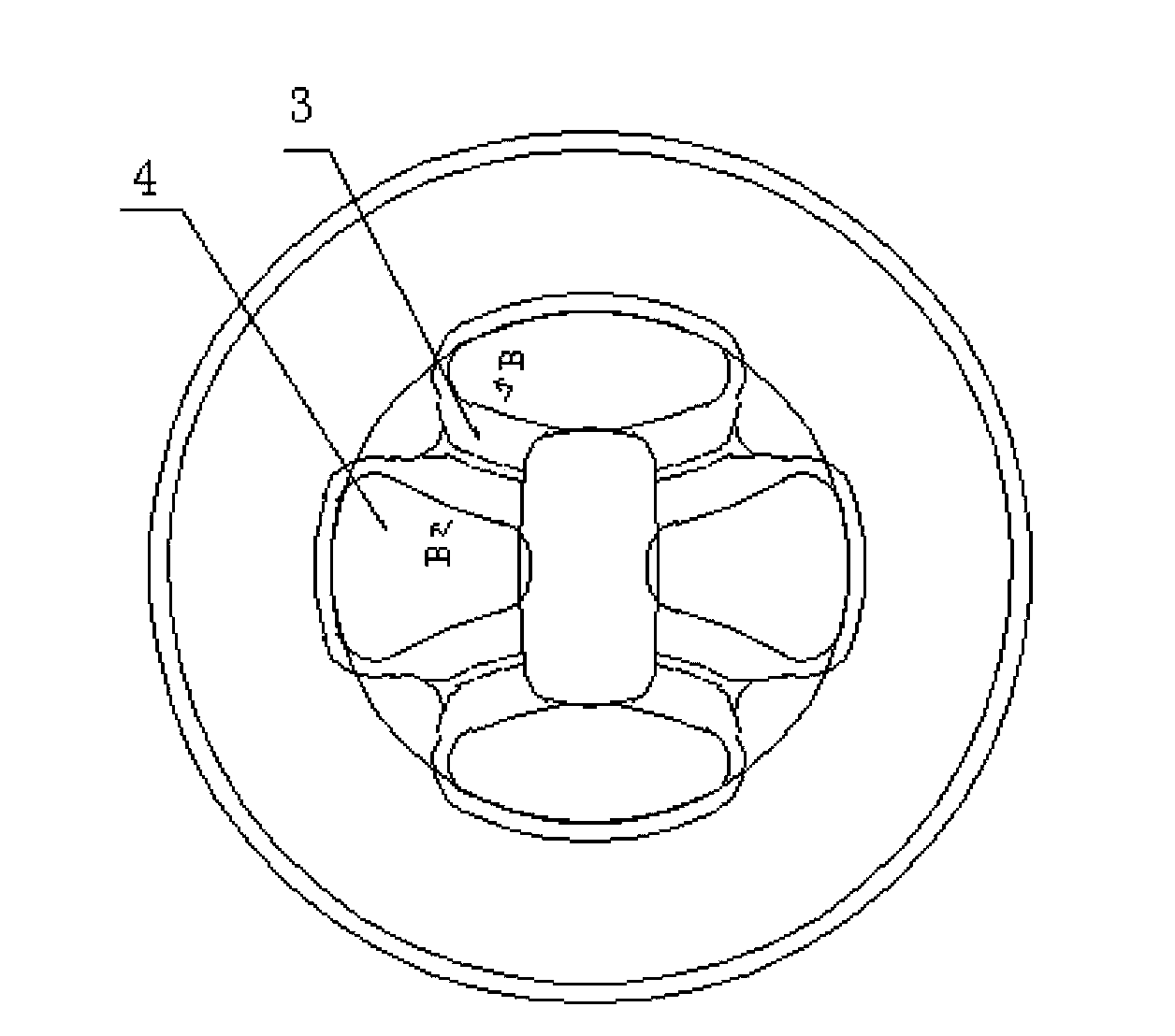
[0016] Embodiment: A structure-improved extrusion die, including a fixedly connected upper die 1 and a lower die 2, the upper end of the upper die 1 is provided with a deflector, the deflector is provided with a bridge 3, and the edge of the bridge 3 Both sides are provided with chamfering structures, and the bridge positions 3 are formed with diversion holes 4, and the core head 5 is provided under the deflector of the upper mold 1, and the lower mold 2 is sequentially provided with connected welding chambers 6, The forming hole 7 and the discharge hole 8, the welding chamber 6 communicates with the split hole 4 of the upper mold 1, the core head 5 of the upper mold 1 is inserted in the forming hole 7 of the lower mold 2, the lower mold 2 The welding chamber 6 is composed of at least two stages of welding chambers 6, and the welding chambers 6 of each stage are arranged in a stepped state with tapered diameters. The material enters from the upper end of the upper mold 1 and fl...


PUM


Abstract

The present invention discloses an extrusion mold with an improved structure. The extrusion mold comprises an upper mold and a lower mold, wherein the upper mold and the lower mold are fixedly connected, the upper end of the upper mold is provided with a diversion plate, bridging positions are arranged inside the diversion plate, the edges of the bridging positions are provided with chamfer structures, shunt holes are formed between the bridging positions, a core head is arranged below the diversion plate of the upper mold, the lower mold is sequentially provided with a soldering chamber, a molding hole and a material discharge hole from top to bottom, the soldering chamber, the molding hole and the material discharge hole are communicated, the soldering chamber is communicated with the shunt hole of the upper mold, the core head of the upper mold is inserted into the molding hole of the lower mold, the soldering chamber of the lower mold comprises at least two stages of sub-soldering chambers, and various stages of the sub-soldering chambers present the stepped alignment state in a gradual diameter reduction manner. According to the present invention, the bridging position edge of the upper mold is designed into the chamber structure so as to provide a diversion effect for the material entering the shunt hole, achieve rapid material shunt and ensure the sufficiency of the material in the molding hole; and after the shunted material enters the soldering chamber and is subjected to multi-stage gradual molding, the whole strength is high, the molded product has a smooth surface, the molding effect is good, and the mold is not easily damaged.

Description

technical field [0001] The invention relates to an extrusion die, in particular to an extrusion die with improved structure. Background technique [0002] All kinds of profiles are formed by extrusion dies. Generally, extrusion dies are composed of an upper die and a lower die. The upper die is equipped with a deflector and a core head. The material flows through the diversion holes on the deflector and then enters the mold. Then it flows into the welding chamber, and after entering the welding chamber, it gathers the flow, and then enters the molding space formed by the core head and the forming hole for extrusion molding, and finally discharges from the discharge hole. At present, the common shunt hole is a straight hole , the material is not easy to enter, the shunting effect is not good, and the welding chamber is a one-layer structure, the material is directly entered into the forming hole for forming after a converging flow, which is not conducive to material forming, ...

Claims


Application Information

Patent Timeline
Patent Type & Authority Applications(China)
IPC IPC(8): B21C25/02
Inventor 涂季冰吕传锋
Owner 捷安特轻合金科技(昆山)股份有限公司
Why Eureka
Try Eureka