
Three-stage horn gate

A horn gate, three-stage technology, applied in the field of gate forms, can solve the problems of unsmooth demoulding of the material head 11, easy deformation of the material head 11, film pulling and deformation, etc., so that it is not easy to deform and break, reduce The effect of molding cycle and effective demoulding

Active Publication Date: 2016-05-04
MITAC PRECISION TECH(KUNSHAN) CORP
View PDF4 Cites 0 Cited by
  • Summary
  • Abstract
  • Description
  • Claims
  • Application Information

AI Technical Summary

Problems solved by technology

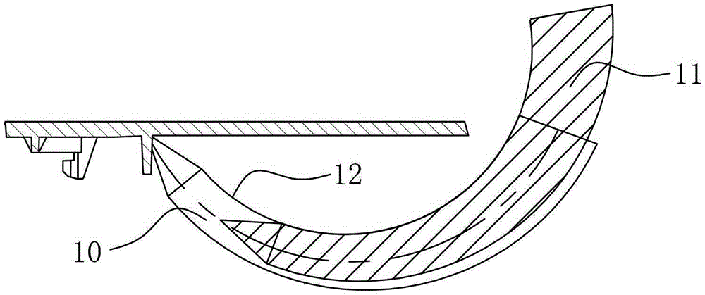
like figure 1 As shown, it is the horn gate 10 in the prior art. When the thimble pushes the material head 11 formed in the horn gate 10 upwards, it moves along the arc direction of the upper surface 12 of the mold cavity, although the horn gate 10 has a smooth shape, but the friction area between the material head 11 and the upper surface 12 of the cavity is about 2 / 3 of the upper surface of the cavity wall, so that the material head 11 is not smooth when demoulding, and the material head 11 is not smooth during the ejection process. The material head 11 is easy to deform and break, which will also make the formed product concave and deformed
[0003] In view of this, it is necessary to provide a corner gate, so that the contact area between the head formed in the corner gate and the upper surface of the mold cavity becomes smaller, so that the material head and the corner gate can be demoulded smoothly, and the molding failure is avoided. The product has the problem of stretching film and deformation

Method used


Image

  • Three-stage horn gate
  • Three-stage horn gate

Examples


Embodiment Construction

[0019] The specific embodiments of the present invention will be described in detail below in conjunction with the accompanying drawings.

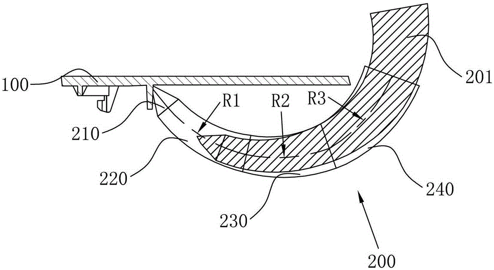
[0020] The three-stage horn gate of the anti-drawing die provided by the present invention is applied to products that require latent glue feeding in the mold, please refer to figure 2 As shown, 100 is a product that requires latent glue injection. The horn gate 200 is shaped like a horn-like curved cone and its cross-sectional size gradually decreases. The horn gate includes:

[0021] Front gate 210, which is located at the joint between the horn gate 200 and the product 100;

[0022] The first gate 220 is connected to the front gate 210, the center line of the first gate 220 is a first arc, and the first arc transitions smoothly with the center line of the front gate 210, so The cross-sectional dimension of the front gate 210 is smaller than the cross-sectional dimension of the first gate 220;

[0023] The second gate 230 is connected...


PUM


Abstract

The invention discloses an Anti-mold drawing three-section type horn gate. The horn gate is shaped like a horn-type curved cone, and the cross section dimension of the horn gate gradually decreases. The horn gate comprises a front-end gate, a first gate, a second gate and a third gate, wherein the front-end gate is arranged at a joint of the horn gate and a product; the first gate is connected with the front-end gate; the center line of the first gate is a first arc which is in smooth transition with the center line of the front-end gate; the second gate is connected with the first gate; the center line of the second gate is a second arc which is in smooth transition with the first arc; the third gate is connected with the second gate; the center line of the third gate is a third arc which is in arc transition with the second arc. The horn gate has the advantages that effective de-molding is realized; the horn gate is difficult to deform or break during ejection; the product quality can be improved; the situations that products are easy to recess by drawing and easy to deform are prevented; the molding period can be shortened; the productivity is improved.

Description

【Technical field】 [0001] The invention relates to a gate form in a mould, in particular to a three-stage horn gate of an anti-draw mold. 【Background technique】 [0002] In the latent injection, the horn-type latent injection is generally used, and the shape of the horn gate is formed by a smooth arc defining the diameters at both ends. Such as figure 1 As shown, it is the horn gate 10 in the prior art. When the thimble pushes the material head 11 formed in the horn gate 10 upwards, it moves along the arc direction of the upper surface 12 of the mold cavity, although the horn gate 10 has a smooth shape, but the friction area between the material head 11 and the upper surface 12 of the cavity is about 2 / 3 of the upper surface of the cavity wall, so that the material head 11 is not smooth when demoulding, and the material head 11 is not smooth during the ejection process. The material head 11 is easily deformed and broken, which will also cause the formed product to be dented...

Claims


Application Information

Patent Timeline
Patent Type & Authority Patents(China)
IPC IPC(8): B29C45/27
CPCB29C45/2708
Inventor 范金兰
Owner MITAC PRECISION TECH(KUNSHAN) CORP
Learn More