High-efficiency straight pedaling bicycle
A bicycle, high-efficiency technology, applied to vehicle parts, vehicle gearboxes, chain/belt transmissions, etc., can solve the problems of unfavorable bicycle speed improvement and maintenance, waste of physical strength, etc., to overcome low mechanical efficiency, improve mechanical efficiency, Avoid the effect of crossover
- Summary
- Abstract
- Description
- Claims
- Application Information
AI Technical Summary
Problems solved by technology
Method used
Image

Examples
Embodiment 1
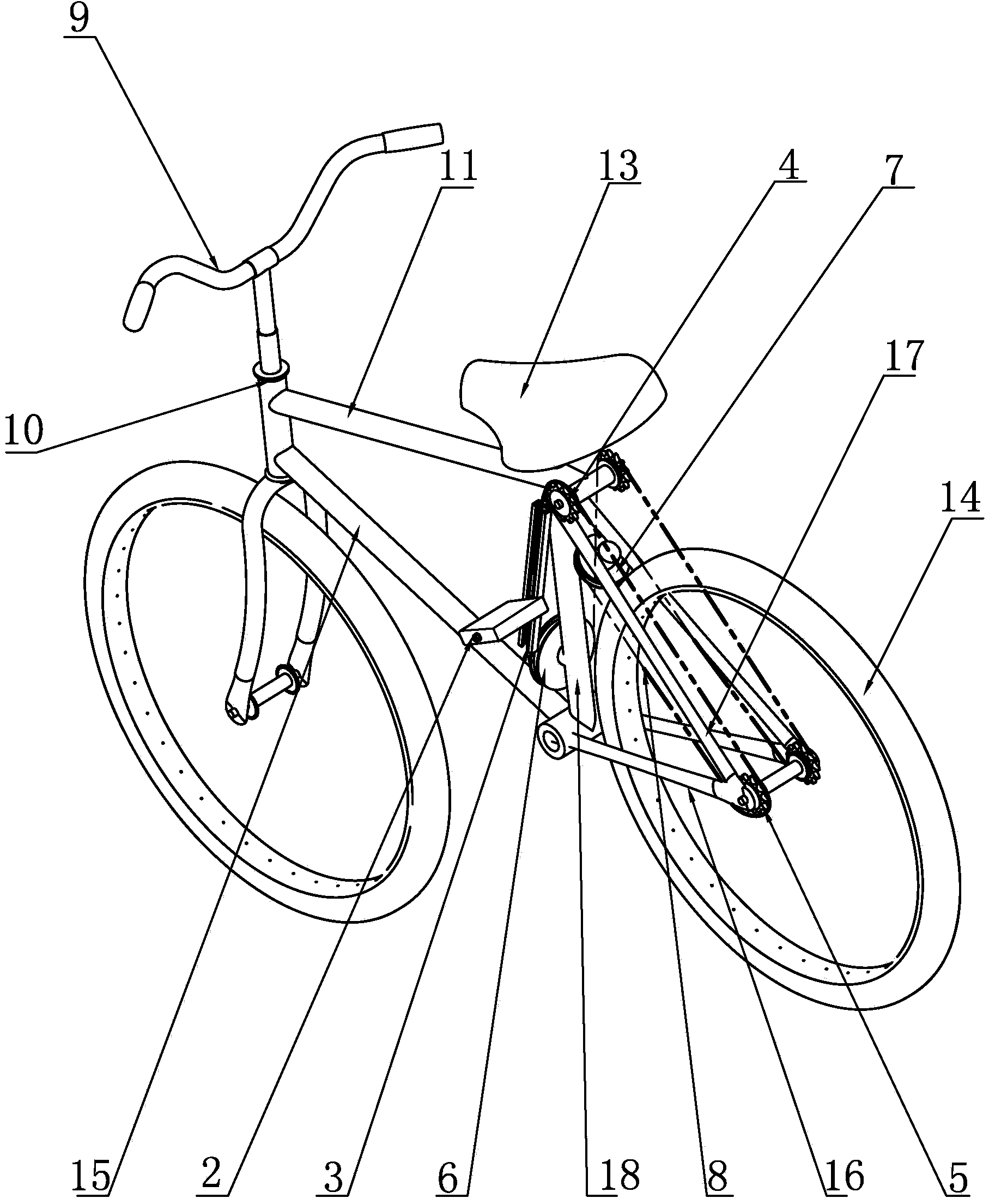
[0030] Such as figure 1 , figure 2 As shown, the high-efficiency straight pedal bicycle of the present invention includes a support mechanism, a transmission structure, a rear wheel 14, a left pedal device and a right pedal device, and the support mechanism includes a handlebar support frame 10, a seat support frame, a lower beam 16, a first The inclined beam 15, the second inclined beam 17 and the third inclined beam 18, the handlebar support frame 10 is welded and fixed below the handlebar 9, the handlebar support frame 10 is placed vertically, and the upper end of the handlebar support frame 10 is fixedly connected to the upper beam 11, the upper beam 11 is placed horizontally, the other end of the upper beam 11 is welded and fixed with the seat support frame, the vehicle seat 13 is installed above the vehicle seat support frame, and the second inclined beam 17 is welded and fixed on the vehicle seat support frame and the rear seat support frame. Between the wheel shafts ...
Embodiment 2
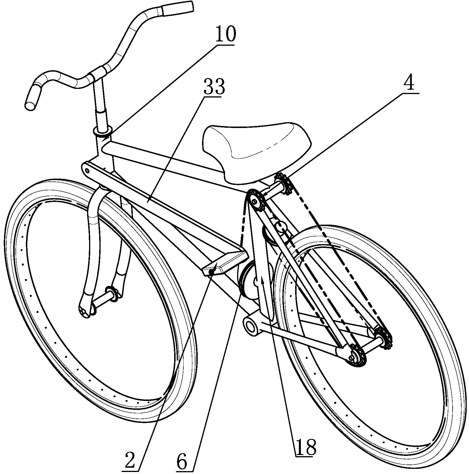
[0042] Such as image 3 As shown, the structural difference between the present embodiment and Embodiment 1 is that the left and right slide plates are removed, the left pedal device includes a left middle rod 33 and a left pedal, the right pedal device includes a right middle rod and a right pedal, and the left middle One end of the rod 33 and the right middle rod is hingedly connected to the handlebar support frame 10 respectively, and is symmetrically arranged with respect to the handlebar support frame 10, and the other end of the left middle rod 33 is fixedly connected to the junction of the left first belt and the left chain , the other end of the right middle bar is fixedly connected to the junction of the first belt and the right chain, and the left pedal 2 and the right pedal are also fixedly welded respectively on the other end of the left middle bar and the right middle bar. The length of the first belt is consistent with the distance between the supporting shaft of...
Embodiment 3
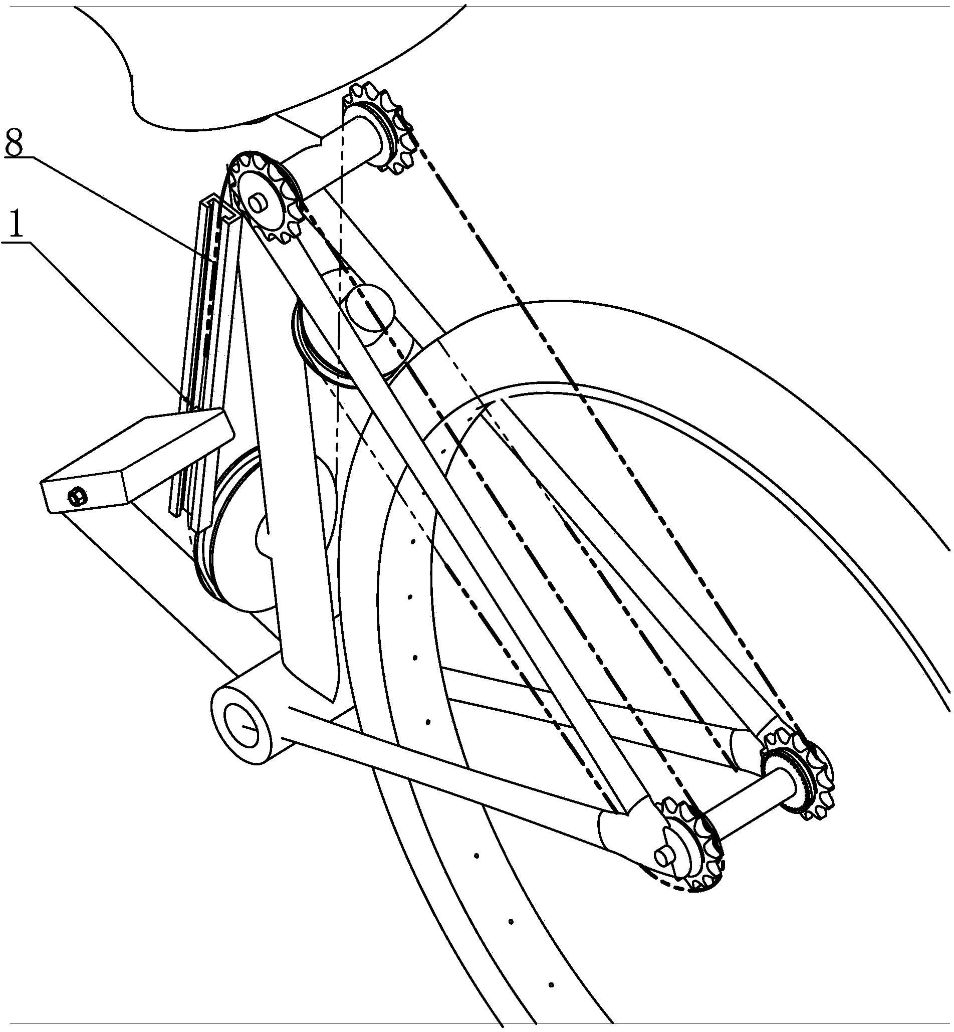
[0047] Such as Figure 4 , Figure 5 , Figure 6 As shown, the structural difference between this embodiment and Embodiment 1 is that the third inclined beam 18 is removed, and the transmission mechanism includes a left slider 3 and a right slider 3', a left slider 1 and a right slider 1', a first middle Flywheel 23 and power transmission shaft, left slide plate 3 and right slide plate 3 ' deviate a certain distance to the left or right side, make the center position of left and right slide plate be positioned at the left side or the right side of rear wheel 14, in left slide plate 3, right slide plate 3' on the middle position of the opposite surface along the length direction of the slide plate from top to bottom are respectively provided with a left through-hole 21, a right through-hole 21', the positions of the left and right through-holes are corresponding, between the left and right through-holes A middle flywheel 23 is installed between them, and a left slider 1 and a...
PUM
 Abstract
Description
Claims
Application Information