An automatic scanning device for ultrasonic testing

A scanning device and ultrasonic testing technology, used in measurement devices, material analysis using sonic/ultrasonic/infrasonic waves, instruments, etc., can solve problems such as high work intensity, unstable data, and inability to fit various styles of welds. , to achieve the effect of convenient operation, reasonable structure and layout, stable and reliable scanning

Active Publication Date: 2016-02-03
SENSE ENG SERVICES
View PDF7 Cites 0 Cited by
  • Summary
  • Abstract
  • Description
  • Claims
  • Application Information

AI Technical Summary

Problems solved by technology

[0006] 1. It needs a special person to push the scanning frame forward. When pushing it manually, it cannot guarantee good coupling and appropriate speed.
During on-site detection, due to the strong magnetic force of the magnetic wheel of the manual scanning device, it takes a lot of force to push the scanning device. speed, resulting in serious dropouts;
[0007] 2. Compared with the imaging above, the manual scanning device will have a great impact on the signal quality due to its difficult operation during the scanning process and some artificial instability factors. Often the data obtained by the manual scanning device on site is very poor. Stable, there are relatively large differences in waveform ups and downs and waveform start;
[0008] 3. Increased the labor intensity of on-site inspectors. The manual scanning device requires a large driving force due to the large magnetic force on the entire device, and the work intensity is also relatively high;
[0009] 4. The design structure is relatively simple and cannot be suitable for various styles of welds
This kind of manual scanning device is often only suitable for some relatively simple butt weld inspections, and cannot be well adapted to some curved surfaces or even spherical surfaces;

Method used


Image

  • An automatic scanning device for ultrasonic testing
  • An automatic scanning device for ultrasonic testing
  • An automatic scanning device for ultrasonic testing

Examples


Embodiment Construction

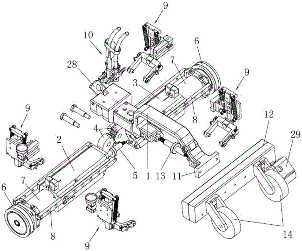
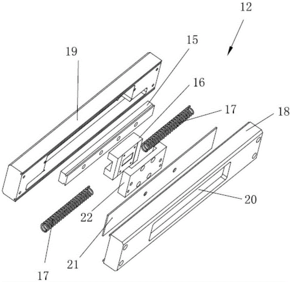
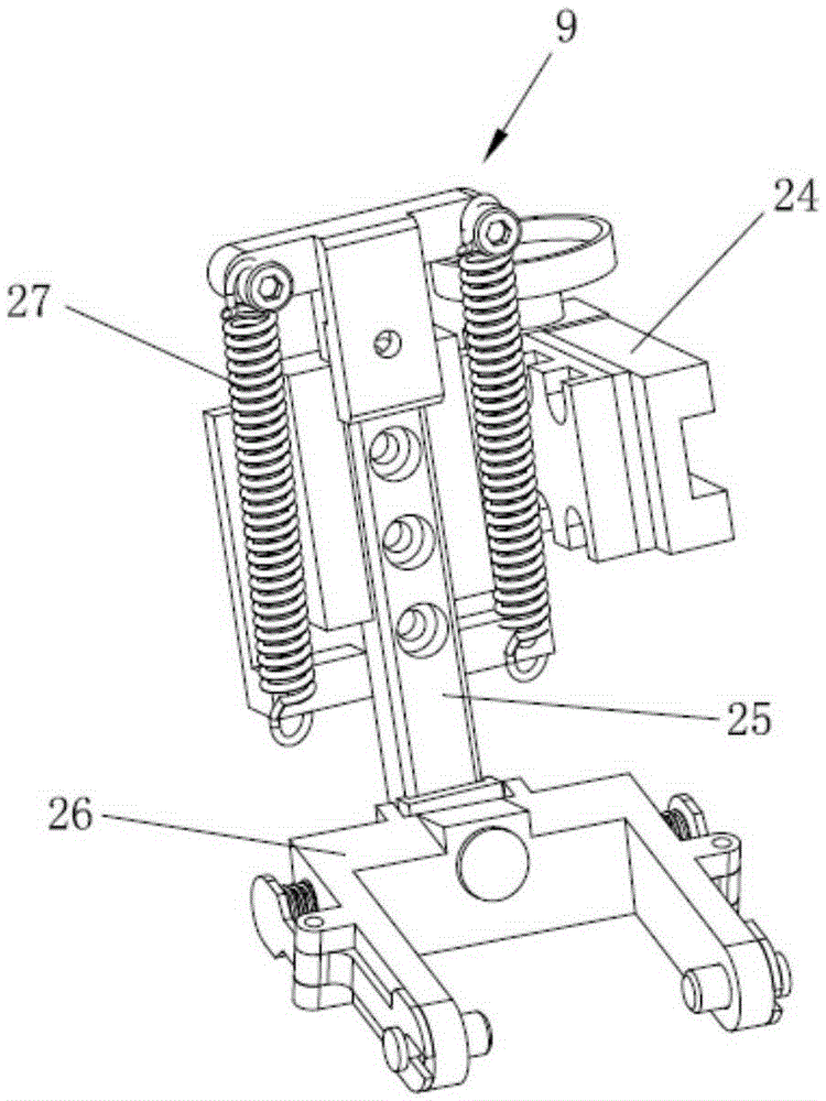
[0028] Attached below figure 1 to attach Figure 4 The technical solutions of the present invention are further described through specific implementation methods.

[0029] An automatic scanning device for ultrasonic detection, comprising a handle assembly 1 and a left scanning arm 2 and a right scanning arm 3 respectively symmetrically arranged at one end of the handle assembly 1, the left scanning arm 2 and the right scanning arm One end of the scanning arm 3 is respectively provided with mutually meshing gears 4, and the bottom of the gear 4 is provided with a first adjustment screw 5 for adjusting the left scanning arm 2 and the right scanning arm 3 to turn up or down. The other ends of the scanning arm 2 and the right scanning arm 3 are respectively provided with first magnetic wheels 6 for ensuring the magnetic attraction force when the automatic scanning device is turned upside down or scanned vertically. The motors 7 on the left scanning arm 2 and the right scanning a...


PUM


Abstract

The invention discloses an automatic scanning device for ultrasonic wave detection. A first magnetic wheel and a second magnetic wheel are arranged on the scanning device, so that the scanning device can be tightly coupled with a metal wall, and inverted or vertical scanning can be met; a first adjusting screw rod and a second adjusting screw rod are arranged on the scanning device, so that the scanning device can be flexibly adjusted and thus is applicable to scanning on different curved surfaces and spherical metal walls; a sliding rear rod component is arranged, the tail part of the scanning device is not blocked and cannot steer because of tight coupling of the magnetic wheels and the metal wall in the steering process; a probe clamp arranged on a scanning arm and a water spraying device arranged on the scanning device are beneficial to detection on coupling of probes, and the scanning is enabled to be stable and reliable. The automatic scanning device is reasonable in structural arrangement, convenient to operate, stable and reliable in scanning, and applicable to scanning on different curved surfaces or spherical metal walls.

Description

technical field [0001] The invention relates to the technical field of ultrasonic detection, in particular to an automatic scanning device for ultrasonic detection. Background technique [0002] With the gradual popularization and application of new ultrasonic detection methods, especially the promotion and application of TOFD detection technology, it will greatly promote the improvement of detection efficiency. [0003] In the traditional A-scan ultrasonic inspection, most of the inspectors manually operate the probe to inspect the workpiece. The limitation of the inspection method determines that the efficiency of this inspection method will be very low. An inspector performs the inspection in full accordance with the high standard requirements. One day The workload is only about 15 meters, and the detection efficiency is very low. In the past two years, the TOFD detection technology has been gradually promoted in China, and their scanning methods are very different from ...

Claims


Application Information

Patent Timeline
Patent Type & Authority Patents(China)
IPC IPC(8): G01N29/265G01N29/28
Inventor 汪月银
Owner SENSE ENG SERVICES
Why Eureka
Try Eureka