Opposite electronic component working equipment

A technology of electronic components and operating equipment, which is applied in the field of opposed electronic component operating equipment, can solve the problems of reducing test operation production efficiency, heavy workload, and test port standby, etc., and achieves the effect of easy expansion of operating area and reduction of table space

Active Publication Date: 2017-08-15
HON PRECISION INC
View PDF11 Cites 0 Cited by
  • Summary
  • Abstract
  • Description
  • Claims
  • Application Information

AI Technical Summary

Problems solved by technology

[0003] 1. Each test port 14a, 14b, 14c, 14d of the test processor is arranged in parallel with test boards 16a, 16b, 16c, 16d at the rear end of the machine platform 10, so when the test port is added due to demand, the body must be constantly Extending and expanding to both sides, resulting in too large body, that is accompanied by the situation that the workshop space is not enough to use
[0004] 2. After the body of the test processor is continuously extended to both sides to expand and add test ports, the IC conveying mechanism 19 must make a farther movement stroke to circle each test seat 15a, 15b, 15c, 15d and the feeding box / lifter 11 and Between the output boxes 13a, 13b, and 13c, it will lead to excessive workload of the IC delivery mechanism 19, and the IC delivery operation cannot be carried out smoothly according to the timing arrangement, which may cause some test ports to stand by and reduce the test operation. production efficiency

Method used


Image

  • Opposite electronic component working equipment
  • Opposite electronic component working equipment
  • Opposite electronic component working equipment

Examples


Embodiment Construction

[0039] In order to make your examiner further understand the present invention, hereby give a preferred embodiment and cooperate with the drawings, as follows in detail:

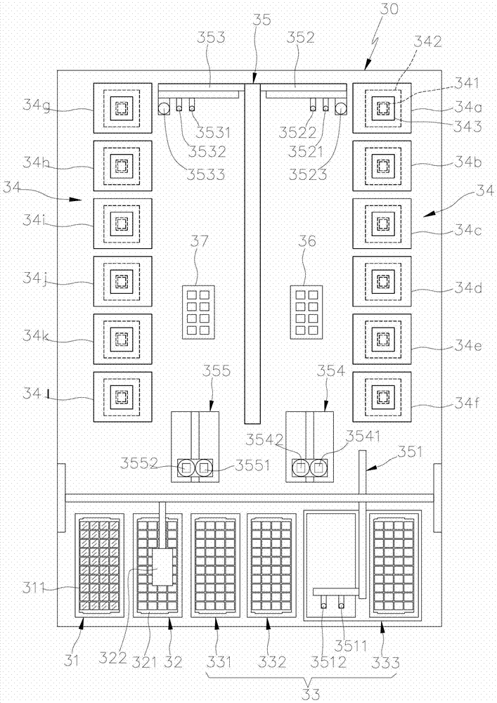
[0040] see image 3 , the opposed type electronic assembly operation equipment of the present invention, which is equipped with a feeding device 31, an empty tray device 32, a material receiving device 33, an operating device 34, and a conveying device 35 on the machine table 30, and is used to control and integrate the actions of each device to A central control unit (not shown in the drawings) for performing automated operations; the feeding device 31 can lift and carry a plurality of trays 311, and each tray 311 can accommodate at least one electronic component to be executed. The empty tray device 32 Can lift and carry a plurality of empty trays 321, and use a tray shifter 322 to transfer the empty trays of the feeding device 31 to the empty tray device 32, or transfer the empty trays on the empty tray d...


PUM


Abstract

The present invention is an opposed electronic component operation equipment. The testing and sorting equipment is mainly equipped with a feeding device, a receiving device, an operating device, a conveying device and a device for controlling and integrating the actions of each device to perform automatic operations. The central control unit, the feeding device is used to accommodate at least one electronic component to be executed, the receiving device is used to accommodate at least one electronic component that has completed the operation, and the conveying device is provided with at least one pick-and-place device for supplying . Electronic components are transported between the receiving device and the operating device; wherein, the operating device is provided with a plurality of oppositely arranged operating areas on at least two sides of the machine table, and at least one bearing seat is provided in each operating area, It is used to carry electronic components and perform operations; in this way, by using the method of setting up the work area opposite, not only the conveying device can effectively shorten the transfer stroke, but also make the machine easy to expand under the premise of effectively reducing the space occupied by the machine table Practical benefits of the work area.

Description

technical field [0001] The invention relates to a kind of opposed electronic component operation equipment which can effectively shorten the transfer stroke of the conveying device, and effectively reduce the occupation of the table space of the machine table, so as to easily expand the operation area. Background technique [0002] see figure 1 , figure 2 , it is China Taiwan Patent Application No. 91105851 IC test handler patent case, this test handler is equipped with feeding box / lifter 11, empty box / lifter 12 and output box 13 respectively at the front end of machine table 10, for The magazine / elevator 11 is filled with ICs to be tested, and the empty magazine / elevator 12 receives the empty supply magazine used by the supply magazine / elevator 11, and can be taken out to the seat of the output box as required, so as to To place the tested ICs, the output box can be subdivided into different levels of output boxes 13a, 13b, 13c to store the tested ICs of different levels...

Claims


Application Information

Patent Timeline
Patent Type & Authority Patents(China)
IPC IPC(8): G01R31/28H01L21/66
Inventor 李子玮
Owner HON PRECISION INC
Why Eureka
Try Eureka