Image capturing lens system

A lens group and lens technology, applied in optics, instruments, optical components, etc., can solve the problems of low manufacturing yield, insufficient balance configuration, and inability to effectively shorten the total length, and achieve the effect of maintaining miniaturization and improving image quality.

Active Publication Date: 2014-06-11
LARGAN PRECISION
View PDF10 Cites 10 Cited by
  • Summary
  • Abstract
  • Description
  • Claims
  • Application Information

AI Technical Summary

Problems solved by technology

With the improvement of semiconductor process technology, the pixel size of the photosensitive element is reduced, and the miniaturized photographic lens is gradually developed to the high-pixel field. The requirements for lens imaging quality are increasing. Therefore, in lens manufacturing, the precision requirements are getting higher and higher. , often reduces the manufacturing yield and increases the manufacturing cost, so a lens architecture that is less sensitive to manufacturing variations has its demand
[0004] Traditional miniaturized optical systems mounted on portable electronic products mostly use a three-piece lens structure, as shown in US Patent No. 7,564,635, which has a three-piece lens configuration with positive refractive power. The quality requirements are even higher, and the conventional three-piece optical system can no longer meet the higher-level photography needs
As shown in U.S. Patent Publication No. 2012 / 0099009, it is a structural design with four lenses, although it can help improve the imaging quality, but the balance configuration of the positive refractive power of this design is insufficient, and it includes a negative lens , resulting in the inability to effectively shorten its total length, resulting in limited application in miniaturized electronic products

Method used


Image

  • Image capturing lens system
  • Image capturing lens system
  • Image capturing lens system

Examples


no. 1 example 》

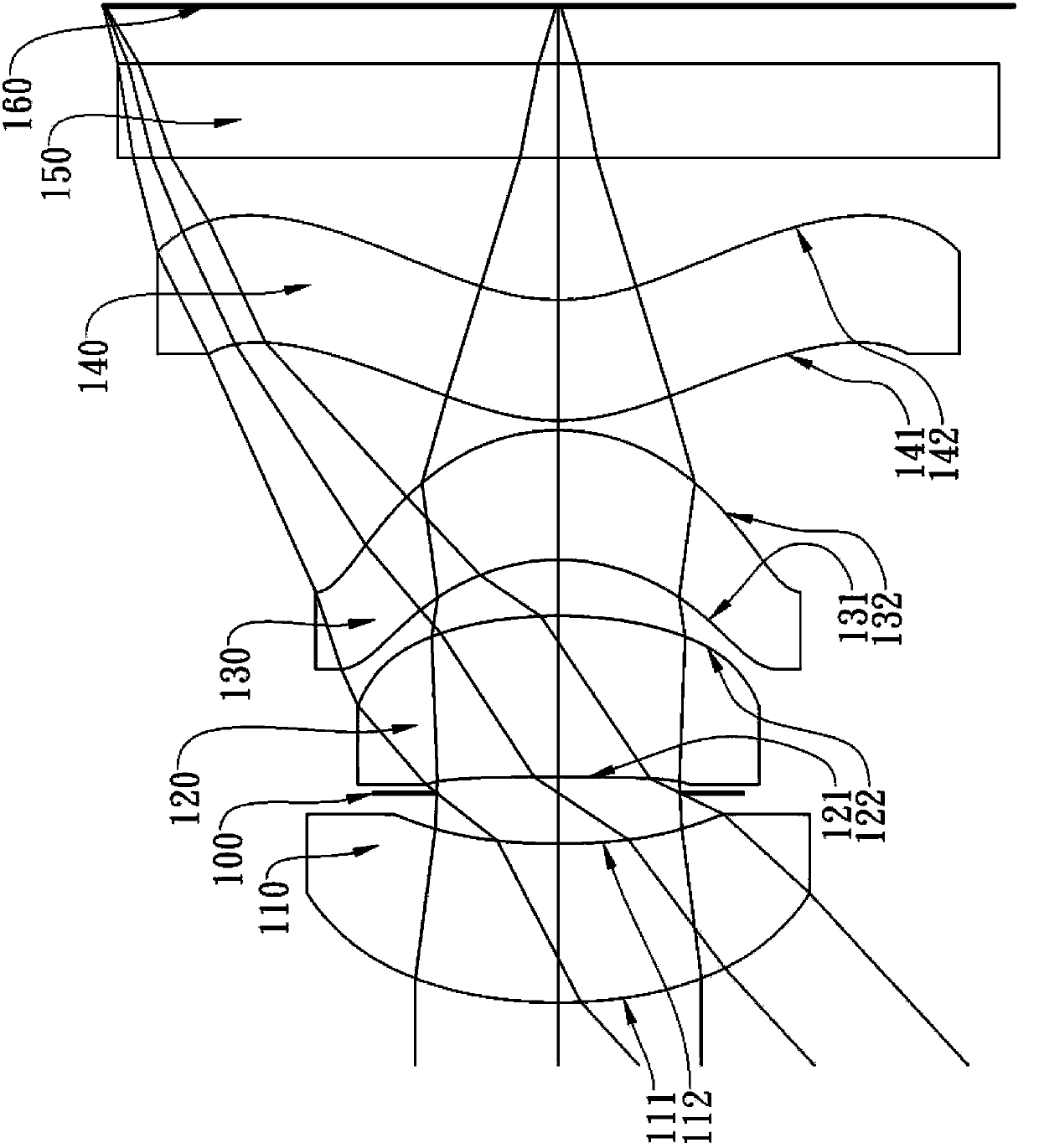
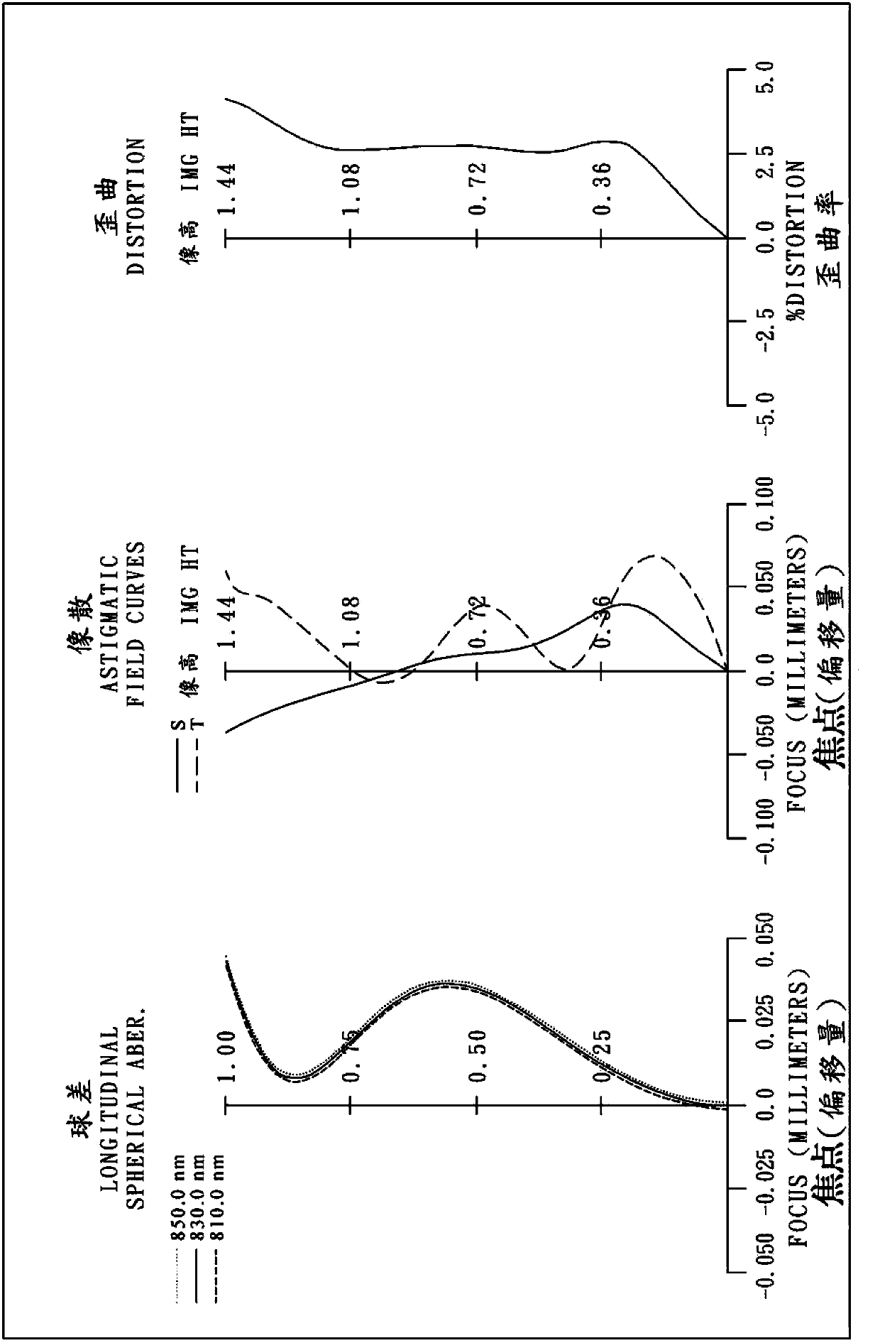
[0073] For a schematic diagram of the optical system see Figure 1A , for aberration curves see Figure 1B . The lens group of the pickup system is mainly composed of four lenses with refractive power, which are sequentially included from the object side to the image side:

[0074] A first lens (110) with positive refractive power, its object side (111) is convex at the near optical axis, its image side (112) is concave at the near optical axis, its material is plastic, and its two sides are is aspheric;

[0075] A second lens (120) with positive refractive power, its object side (121) is concave at the near optical axis, its image side (122) is convex at the near optical axis, its material is plastic, and its two sides are is aspheric;

[0076] A third lens (130) with positive refractive power, its object side (131) is concave at the near optical axis, its image side (132) is convex at the near optical axis, its material is plastic, and its two sides are is aspherical; an...

no. 2 example 》

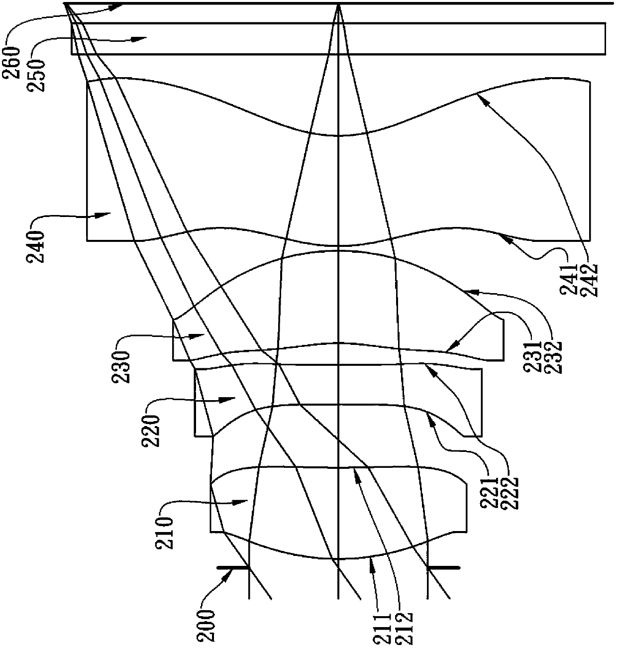
[0101] For a schematic diagram of the optical system see Figure 2A , for aberration curves see Figure 2B . The lens group of the pickup system is mainly composed of four lenses with refractive power, which are sequentially included from the object side to the image side:

[0102] A first lens (210) with positive refractive power, its object side (211) is convex at the near optical axis, its image side (212) is concave at the near optical axis, its material is plastic, and its two sides are is aspheric;

[0103] A second lens (220) with positive refractive power, its object side (221) is convex at the near optical axis, its image side (222) is convex at the near optical axis, its material is plastic, and its two sides are is aspheric;

[0104] A third lens (230) with positive refractive power, its object side (231) is concave at the near optical axis, its image side (232) is convex at the near optical axis, its material is plastic, and its two sides are is aspherical; an...

no. 3 example 》

[0114] For a schematic diagram of the optical system see Figure 3A , for aberration curves see Figure 3B . The lens group of the pickup system is mainly composed of four lenses with refractive power, which are sequentially included from the object side to the image side:

[0115] A first lens (310) with positive refractive power, its object side (311) is convex at the near optical axis, its image side (312) is concave at the near optical axis, its material is plastic, and its two sides are is aspheric;

[0116] A second lens (320) with positive refractive power, its object side (321) is convex at the near optical axis, its image side (322) is convex at the near optical axis, its material is plastic, and its two sides are is aspheric;

[0117] A third lens (330) with positive refractive power, its object side (331) is concave at the near optical axis, its image side (332) is convex at the near optical axis, its material is plastic, and its two sides are is aspherical; an...


PUM


Abstract

This disclosure provides an image capturing lens system, in order from an object side to an image side comprising: a first lens element with positive refractive power having a convex object-side surface and a concave image-side surface; a second lens element with positive refractive power; a third lens element with positive refractive power; and a fourth lens element with positive refractive power having a convex object-side surface, a concave at a paraxial region and convex at a peripheral region image-side surface, and both of the object-side and image-side surfaces thereof being aspheric. By arranging the four lens elements with refractive power, the refractive power can be applied on the four lens elements in a uniform manner, so as to reduce the sensitivity of the radius of curvature, and the thickness of the center or the like to produce an aberrance to improve the qualified rate of the production.

Description

technical field [0001] The invention relates to an image pickup system lens group, in particular to an image pickup system lens group applicable to infrared and visible light bands. Background technique [0002] In recent years, with the rise of portable electronic products with photography functions, the demand for miniaturized photography lenses in the market is increasing day by day. The photosensitive element of a general photographic lens is nothing more than a photosensitive coupling device (Charge Coupled Device, CCD) or a complementary metal oxide semiconductor element. [0003] (Complementary Metal-Oxide Semiconductor Sensor, CMOS Sensor) two. With the improvement of semiconductor process technology, the pixel size of the photosensitive element is reduced, and the miniaturized photographic lens is gradually developed to the high-pixel field. The requirements for lens imaging quality are increasing. Therefore, in lens manufacturing, the precision requirements are ge...

Claims


Application Information

Patent Timeline
IPC IPC(8): G02B13/18G02B13/14G02B13/00G02B1/04
CPCG02B13/004G02B13/18
Inventor 薛钧哲蔡宗翰陈纬彧
Owner LARGAN PRECISION
Why Eureka
Try Eureka