Method and device for planning spatial motion of intelligent arm

A space motion and smart arm technology, applied in the field of smart arm control, can solve problems such as complex motion planning, no consideration of turntable automatic control, and reduced actual performance of the smart arm

Active Publication Date: 2014-06-11
SANY AUTOMOBILE MFG CO LTD
View PDF6 Cites 3 Cited by
  • Summary
  • Abstract
  • Description
  • Claims
  • Application Information

AI Technical Summary

Problems solved by technology

[0006] Since the spatial motion planning of the boom based on the three-dimensional coordinate calculation method shown in formula (1) is very complicated, many patents related to smart booms avoid the spatial motion planning of the boom and directly use the boom The movement of the space is simplified to a linear movement, that

Method used


Image

  • Method and device for planning spatial motion of intelligent arm
  • Method and device for planning spatial motion of intelligent arm
  • Method and device for planning spatial motion of intelligent arm

Examples


Embodiment Construction

[0043] It should be noted that, in the case of no conflict, the embodiments of the present invention and the features in the embodiments can be combined with each other. The present invention will be described in detail below with reference to the accompanying drawings and examples.

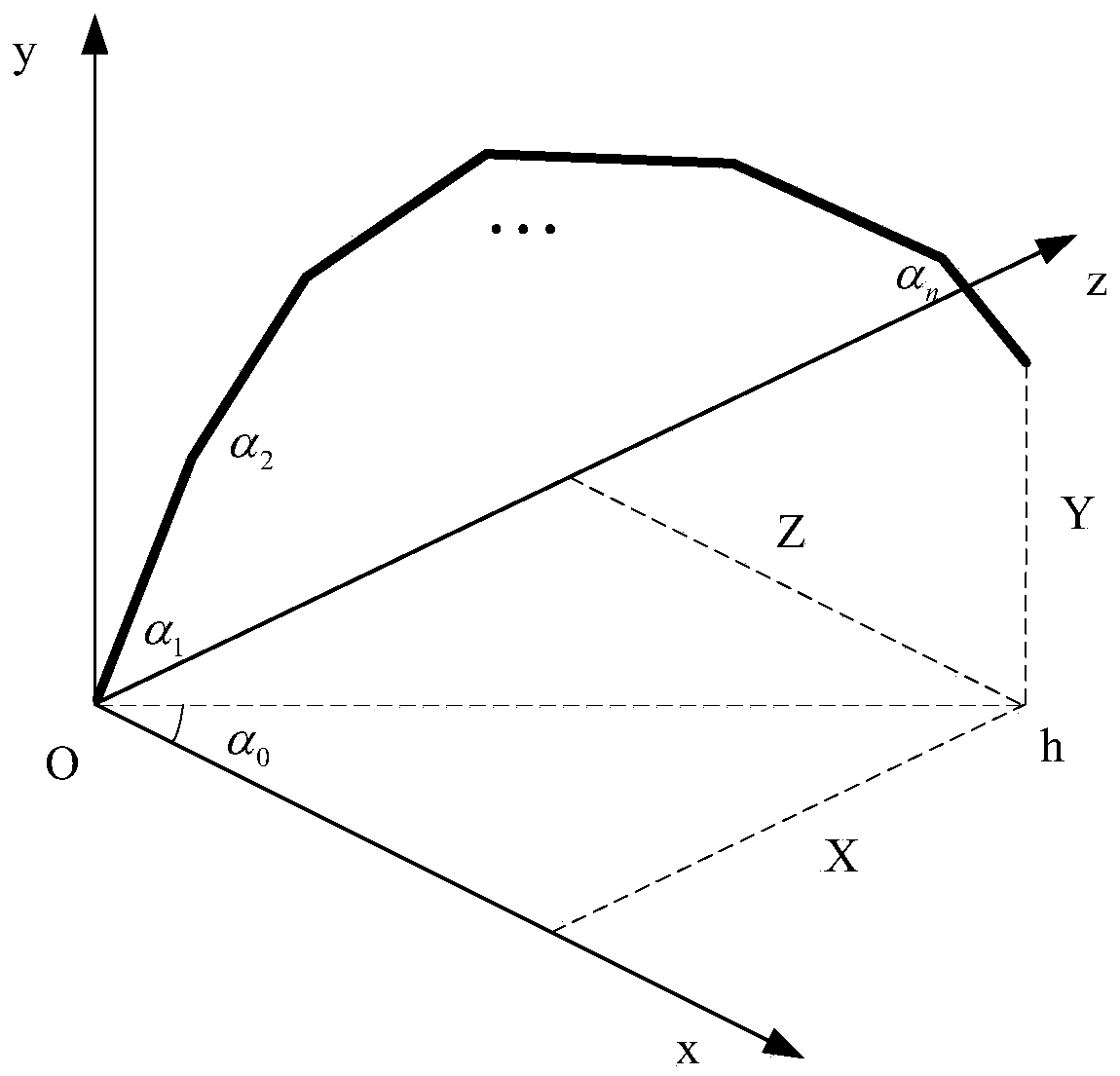
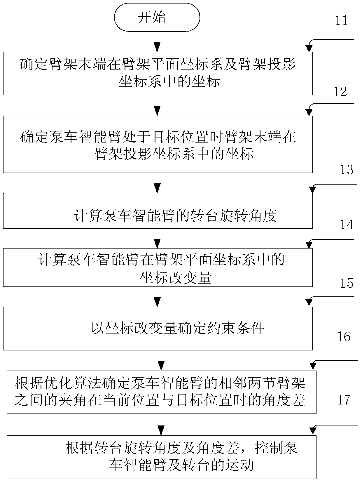
[0044] figure 2 It is a flow chart of the intelligent arm space motion planning method provided by the embodiment of the present invention, the intelligent arm space motion planning method is applied to the intelligent arm with n-section arms, wherein n is greater than or equal to 2; figure 2 As shown, the intelligent arm spatial motion planning method includes:

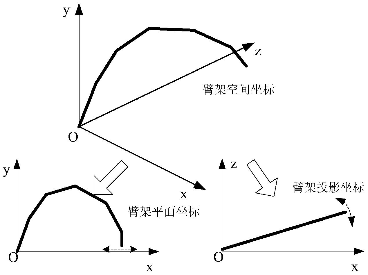
[0045] Step 11: According to the coordinates of the boom end in the boom space coordinate system when the smart arm is in the current position, determine the first coordinate of the boom end in the boom plane coordinate system and the first coordinate in the boom projection coordinate system Two coordinates;

[0046] Specific as ...


PUM


Abstract

The invention discloses a method and device for planning spatial motion of an intelligent arm. The method comprises the steps of determining first coordinates of the tail ends of arm rests in an arm rest plane-coordinate system and second coordinates of the tail ends of the arm rests in an arm rest projected coordinate system, determining third coordinates of the tail ends of the arm rests in the arm rest projected coordinate system when the intelligent arm is located at the target position, calculating and obtaining the rotating angle of a rotating table of the intelligent arm, calculating the coordinate change quantity of the intelligent arm in the arm rest plane-coordinate system, determining the angle difference of the included angle between two adjacent arm rests of the intelligent arm according to an optimization algorithm, and respectively controlling the motion of the rotating table and the arm rests of the intelligent arm. According to the method for planning the spatial motion of the intelligent arm, the movement of the intelligent arm in the space can be conveniently and automatically controlled, and the use performance of the intelligent arm rests is improved.

Description

technical field [0001] The invention relates to the technical field of intelligent arm control, in particular to a method and device for spatial motion planning of an intelligent arm. Background technique [0002] The coordinates (X Y Z) of the boom of the concrete pump truck (such as the smart arm) in the three-dimensional space can be as follows: figure 1 As shown, the three-dimensional space can be determined as follows: in the space accessible by the boom of the pump truck, take the hinge joint between the turntable of the pump truck and the first section of the boom as the origin of coordinates, and take the direction of the hopper of the body as the positive semi-axis of x , taking the direction perpendicular to the vehicle body as the positive semi-axis of the y-axis, according to the right-hand rule of the Cartesian coordinate system, the z-axis can be determined. Of course, other points can be used as the origin of the coordinates according to actual needs, and oth...

Claims


Application Information

Patent Timeline
IPC IPC(8): G05D3/00
Inventor 代晴华王建明曾启贾剑峰
Owner SANY AUTOMOBILE MFG CO LTD
Why Eureka
Try Eureka