Data center network structure and routing method thereof
A network structure and data center technology, applied in the computer field, can solve the problems of slow expansion, high cost, and high switch price
- Summary
- Abstract
- Description
- Claims
- Application Information
AI Technical Summary
Problems solved by technology
Method used
Image
Examples
Embodiment 1
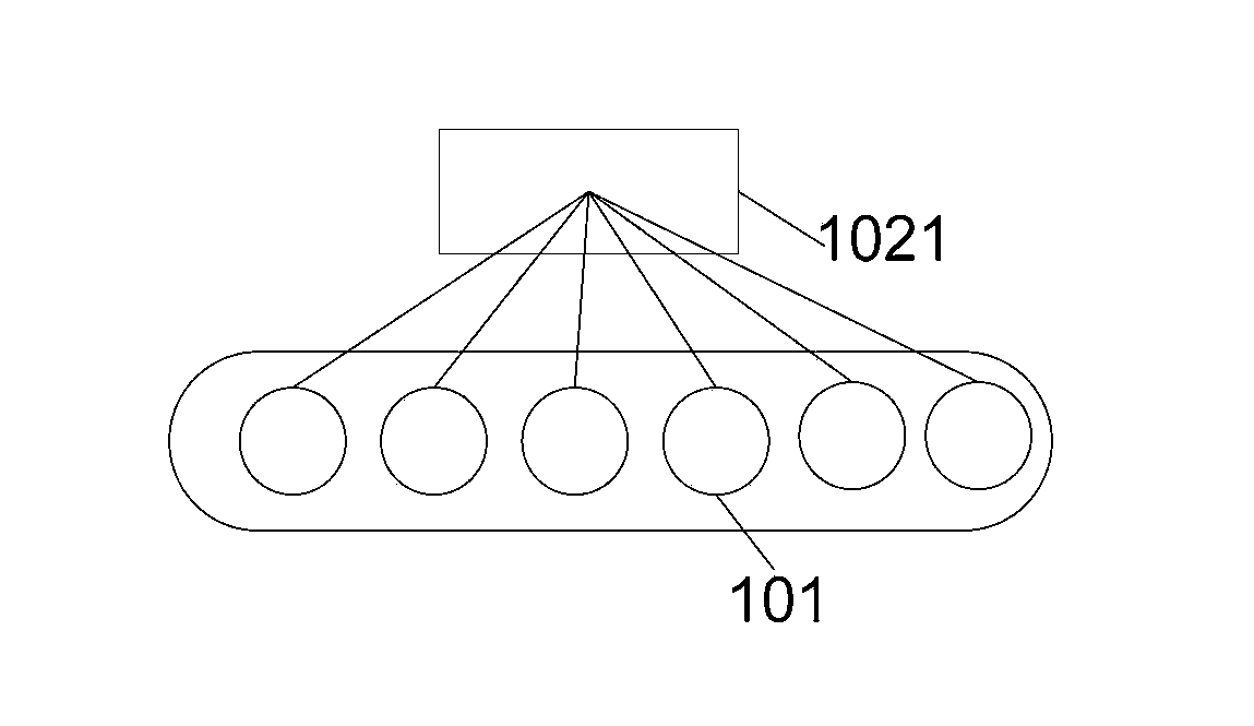
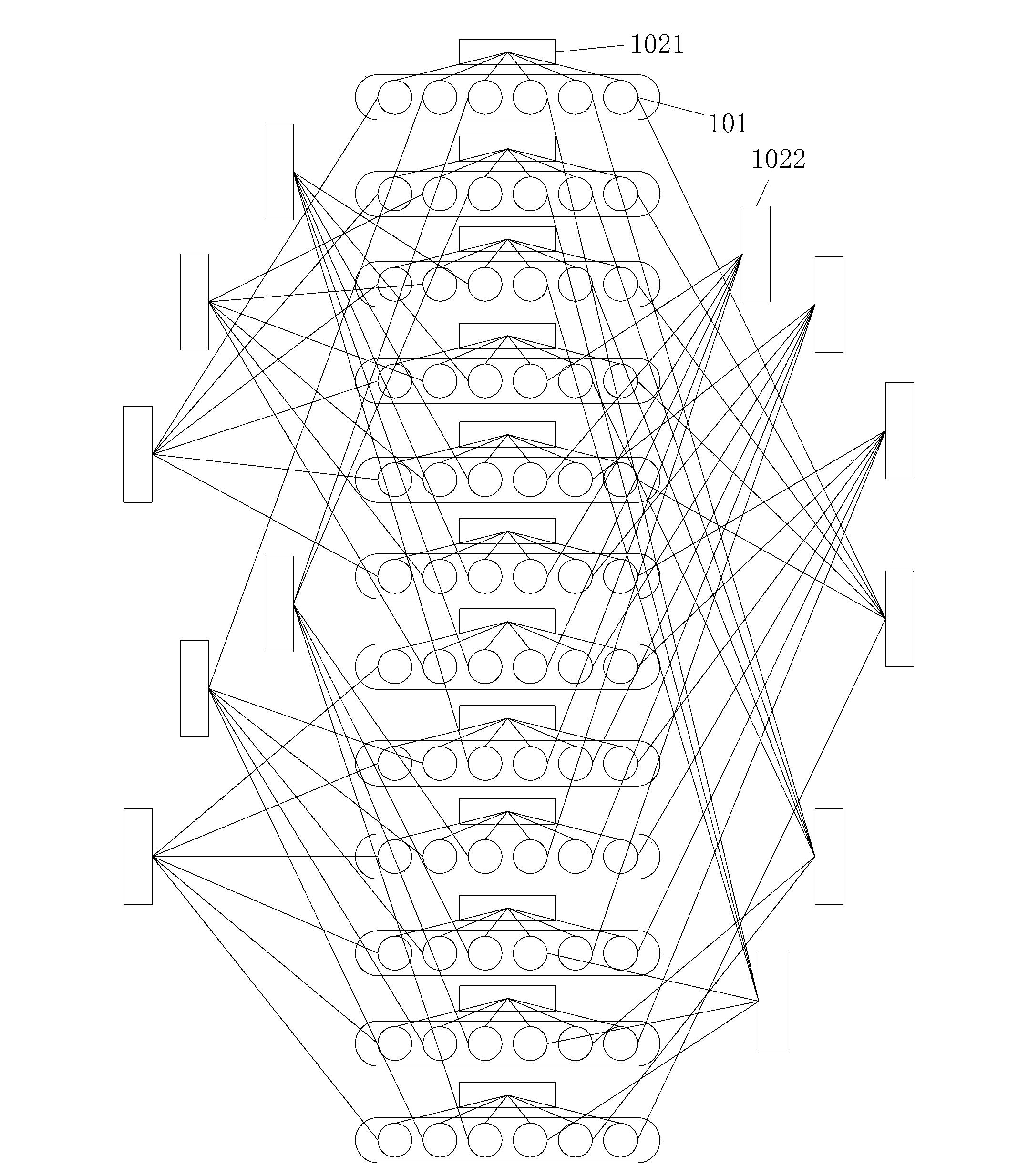
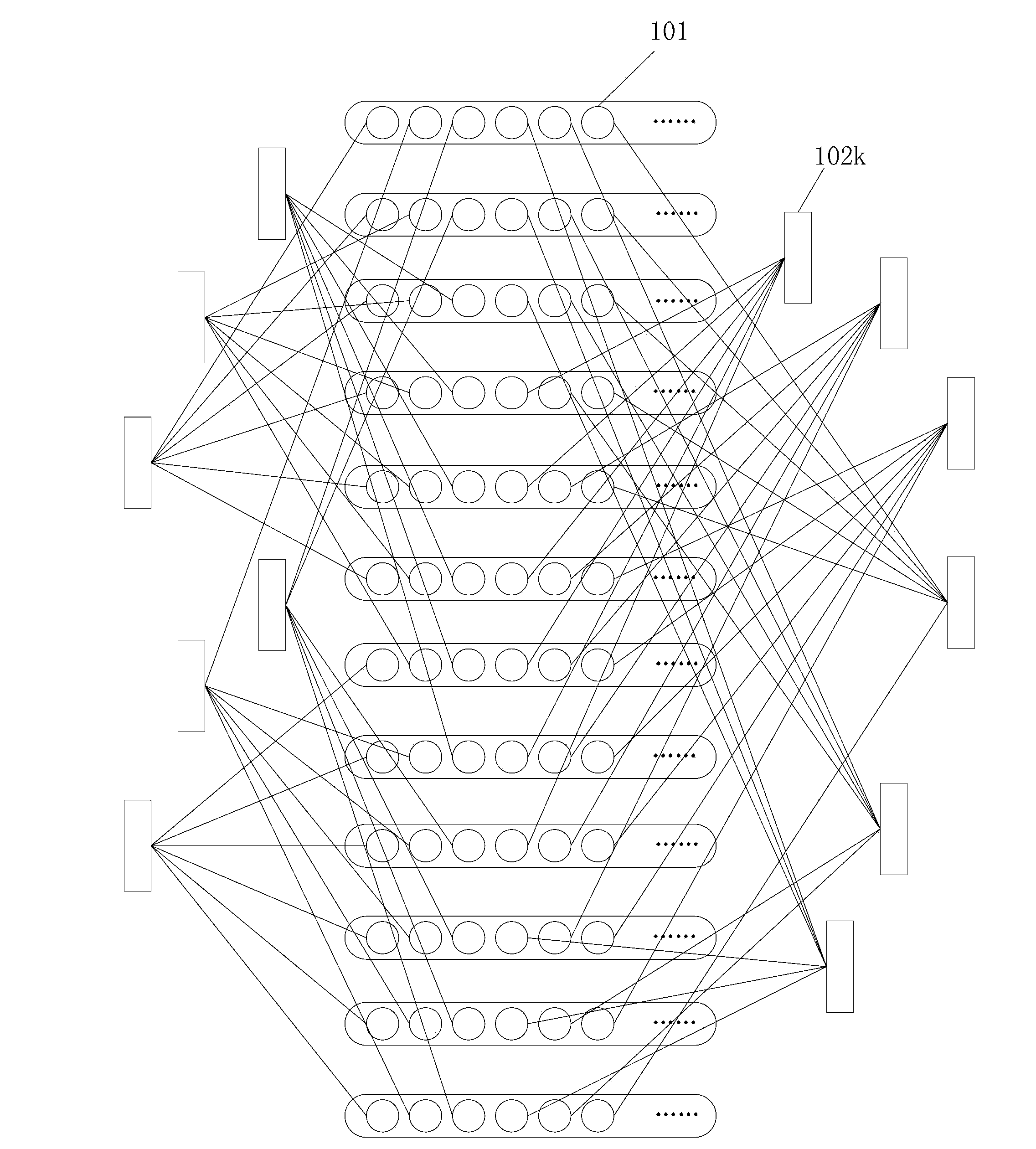
[0087] Taking n=6, b=2 as an example, the data center network structure provided by the embodiment of the present invention will be further described. That is to say, in this embodiment, the switches are all 6-port switches. The network structure includes k (k>1 and k is an integer) layer network, and the structure of each layer network is described below.
[0088] figure 1 It is a schematic diagram of the layer 1 network of the data center network structure provided by this embodiment. see figure 1 , the layer 1 network includes 6 servers 101 and 1 layer 1 switch 1021 , and each server 101 is connected to a port of the layer 1 switch 1021 respectively.
[0089] figure 2 It is a schematic diagram of the layer 2 network of the data center network structure in this embodiment. see figure 2 , the layer 2 network includes 12 (2×6) layer 1 networks and 6 groups of layer 2 switches 1022, each group of layer 2 switches 1022 includes 2 layer 2 switches 1022, in the 12 layer 1 n...
Embodiment 2
[0098] Taking n=4, b=n as an example, the data center network structure provided by the embodiment of the present invention will be further described. That is to say, in this embodiment, the switches are all 4-port switches. The network structure includes k (k>1 and k is an integer) layer network, and the structure of each layer network is described below.
[0099] Figure 4 It is a schematic diagram of the layer 1 network of the data center network structure provided by this embodiment. see Figure 4 , the layer 1 network includes 4 servers 201 and a layer 1 switch 2021 , each server 201 is connected to a port of the layer 1 switch 2021 .
[0100] Figure 5 It is a schematic diagram of the layer 2 network of the data center network structure in this embodiment. see Figure 5 , the layer 2 network includes 16 (4×4) layer 1 networks and 4 groups of layer 2 switches 2022, each group of layer 2 switches 2022 includes 4 layer 2 switches 2022, the 16 layer 1 networks The serv...
Embodiment 3
[0112] The embodiment of the present invention provides a routing method based on the data center network structure provided in Embodiment 1 or 2, see Figure 7 , the method includes:
[0113] 301: In the k-th layer network, find out the first intermediate server reachable by the source server, and the first intermediate server and the destination server are in the same k-1 layer network;
[0114]302: Find the f+1th intermediate server reachable by the fth intermediate server in the k-f layer network where the fth intermediate server is located. The f+1th intermediate server and the destination server are in the same k-f-1 layer network until In the layer 1 network where the k-1th intermediate server is located, find out the kth intermediate server reachable by the k-1th intermediate server, the kth intermediate server is the destination server, k>f≥1.
[0115] The embodiment of the present invention finds the f+1th intermediate server reachable by the fth intermediate server...
PUM
 Abstract
Description
Claims
Application Information
 - R&D
- Intellectual Property
- Life Sciences
- Materials
- Tech Scout
- Unparalleled Data Quality
- Higher Quality Content
- 60% Fewer Hallucinations
Browse by: Latest US Patents, China's latest patents, Technical Efficacy Thesaurus, Application Domain, Technology Topic, Popular Technical Reports.
© 2025 PatSnap. All rights reserved.Legal|Privacy policy|Modern Slavery Act Transparency Statement|Sitemap|About US| Contact US: help@patsnap.com


