Son-mother gas filling station

A gas cylinder and luck technology, applied in the direction of gas/liquid distribution and storage, special distribution devices, equipment loaded into pressure vessels, etc., can solve problems such as no discovery, achieve fast expansion speed, increase gas filling capacity, and simplify the process The effect of the process

Inactive Publication Date: 2010-07-21
沈军
View PDF8 Cites 5 Cited by
  • Summary
  • Abstract
  • Description
  • Claims
  • Application Information

AI Technical Summary

Problems solved by technology

So far, when this case is applied for, no gas cylinder trailers larger than 20MPa have been found on the market for sale.

Method used


Image

  • Son-mother gas filling station
  • Son-mother gas filling station
  • Son-mother gas filling station

Examples


Embodiment 1

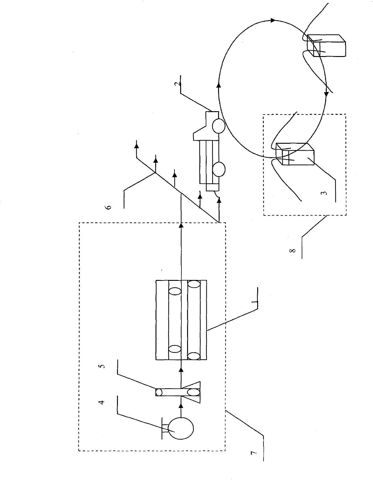
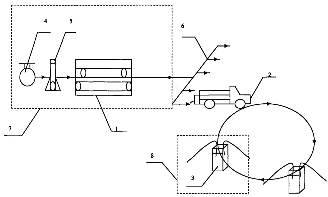
[0049] figure 1 It is the flow chart of the parent-child filling station with pipeline natural gas as the parent station; 1 indicates the compressor; 2 indicates the gas cylinder of the luck trailer; 3 indicates the filling machine; 4 indicates the natural gas pipeline; 5 indicates the dehydration, filtering and drying device; 6 indicates Inflatable busbar; 7, the dotted line box indicates the mother station area; 8, the dotted line box indicates the substation area or gas filling terminal.

[0050] Process implementation process:

[0051] In the 7 mother station, the natural gas is pumped from the 4 natural gas pipeline and then pressurized to 25-30MPa by the 5 dehydration, filtration and drying device to the 1 compressor, and the gas cylinder of the luck trailer is filled with gas through the 6 inflatable bus bar, and the trailer gas cylinder is filled with gas The pressure is 25MPa, and it is transported to each corresponding sub-station to be connected with the filling ma...

Embodiment 2

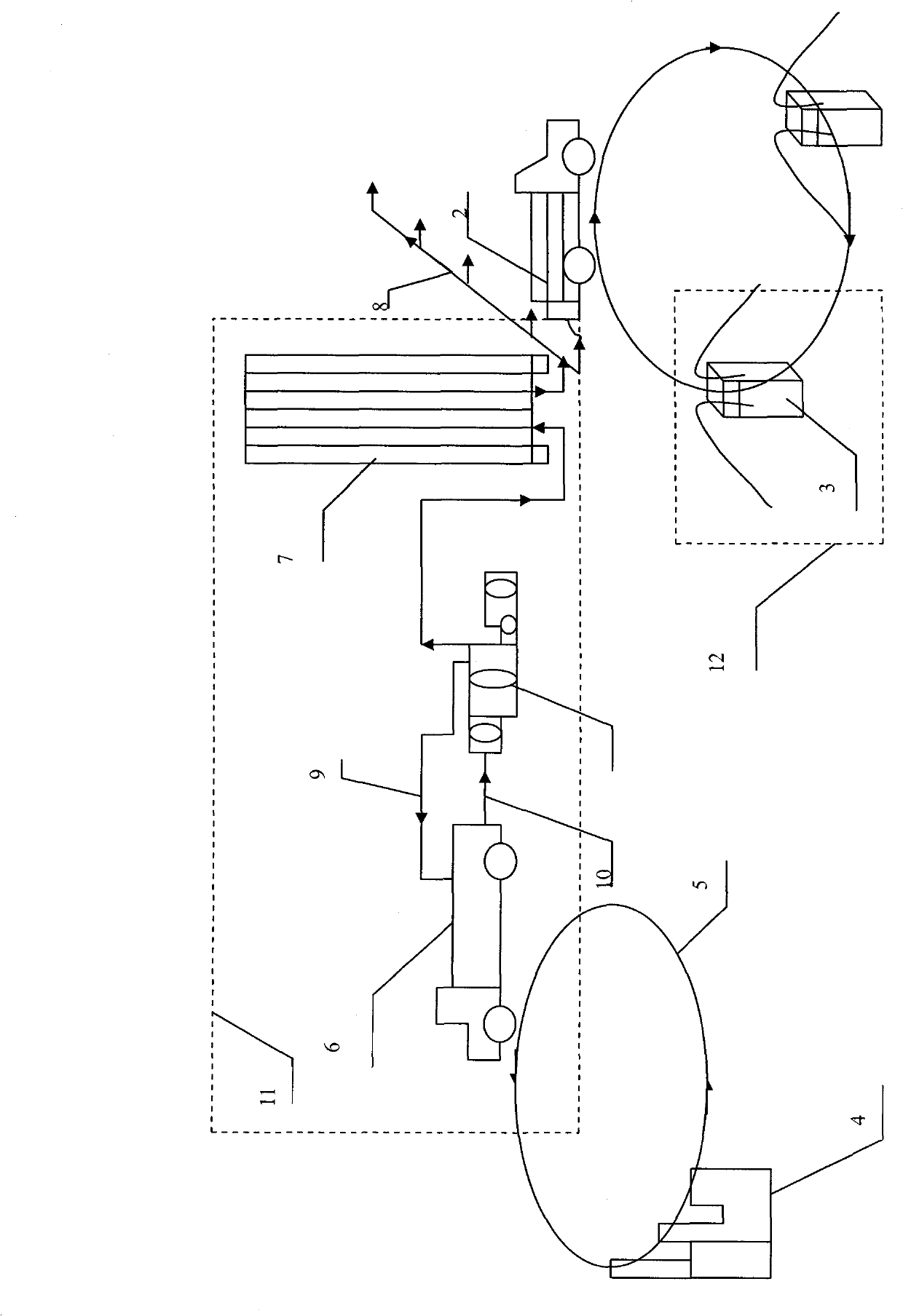
[0053] figure 2 It is the flow chart of the mother-to-child refueling station with the LNG gasification station as the parent station; 1 represents the compressor; 2 represents the gas cylinder of the luck trailer; 3 represents the gas dispenser; 4 represents the LNG factory or receiving station; 5 represents the LNG tanker Circular transportation between the factory and the gasification station; 6 indicates the LNG liquid tank car; 7 indicates the vaporizer; 8 indicates the gas-filled bus; 9 indicates the gas phase unloading; 10 indicates the LNG liquid phase channel; Boxes indicate substation areas or refueling terminals.

[0054] Process implementation process:

[0055] LNG liquid tank car 6 is transported circularly between the 5th factory and the gasification station. In the 11 mother station, the 6LNG liquid tank car is connected to the cryopump, and the LNG liquid in the 6 tank car flows into the cryogenic pump through 10 through 9 gas phase unloading. The cryogenic ...


PUM


Abstract

The invention relates to a son-mother gas filling station, which consists of a compressor or a low-temperature pump, a trailer cylinder and a gas filling machine. The son-mother gas filling station is technically characterized in that the compressor or the low-temperature pump increases outlet pressure to fill gas into the trailer cylinder, so that the pressure in the trailer cylinder is higher than the pressure in a vehicle cylinder, and the gas filling for the vehicle cylinder is completed through connection with the gas filling machine. The technical scheme greatly simplifies the technological flow, and is simple, efficient, energy-saving and safer. The terminal gas filling part of the son-mother gas filling station requires no power-driven power supply or transformer, thereby saving the labor and the cost of power consumption, and the gas filling terminal (son station) part can be easily constructed; the area directly occupied by the equipment is small, and the son station expanding speed is high; the investment in large-scale equipment such as a compressor leveling body, a hydraulic leveling body and the like is saved; the zero pollution and zero emission are realized; and the gas filling capability can be easily enhanced, and the invention avoids the problems of power consumption of the son station, mechanical wear and the like in the prior art. The gas filling terminal part of the son-mother gas filling station can fill gas into the vehicle cylinder in any place in a movable or fixed way.

Description

technical field [0001] The mother-to-child gas filling station involved in the present invention is composed of a compressor or a cryopump, a trailer gas cylinder, and a gas filling machine, also known as a gas filling system, which is suitable for various gases, such as natural gas, hydrogen, etc., and belongs to the field of supporting supply of energy infrastructure equipment . Background technique [0002] In order to refuel natural gas and hydrogen fueled vehicles, a sales network is currently formed in the form of "child-mother refueling stations" to refuel automobile cylinders. The present invention is illustrated by taking a natural gas fueled vehicle as an example, and is also applicable to hydrogen. [0003] The parent gas filling station takes gas from the natural gas pipeline, adjusts the pressure, measures, dehydrates and filters it, and then enters the compressor to boost the pressure to fill the gas cylinder of the luck trailer. [0004] Another form of pare...

Claims


Application Information

Patent Timeline
Patent Type & Authority Applications(China)
IPC IPC(8): B67D7/02F17C5/04
CPCY02E60/321Y02E60/32
Inventor 沈军
Owner 沈军
Why Eureka
Try Eureka