Magnetic resonance imaging apparatus and bed device

一种磁共振成像、核磁共振的技术,应用在磁共振测量、测量装置、诊断等方向,能够解决无法增大电磁波输出、无法增大无线输出、动态范围降低等问题

Active Publication Date: 2014-06-11
TOSHIBA MEDICAL SYST CORP
View PDF8 Cites 7 Cited by
  • Summary
  • Abstract
  • Description
  • Claims
  • Application Information

AI Technical Summary

Problems solved by technology

[0006] More specifically, in the MRI apparatus, in order to suppress the influence on the reception sensitivity of the weak MR signal radiated from the subject, the electromagnetic wave used for wireless communication between the control side of the MRI apparatus and the RF coil apparatus cannot be increased. Output
In the case where the wireless output cannot be increased, the dynamic range is reduced due to signal loss when the transmitted signal propagates through space

Method used


Image

  • Magnetic resonance imaging apparatus and bed device
  • Magnetic resonance imaging apparatus and bed device
  • Magnetic resonance imaging apparatus and bed device

Examples


no. 1 approach

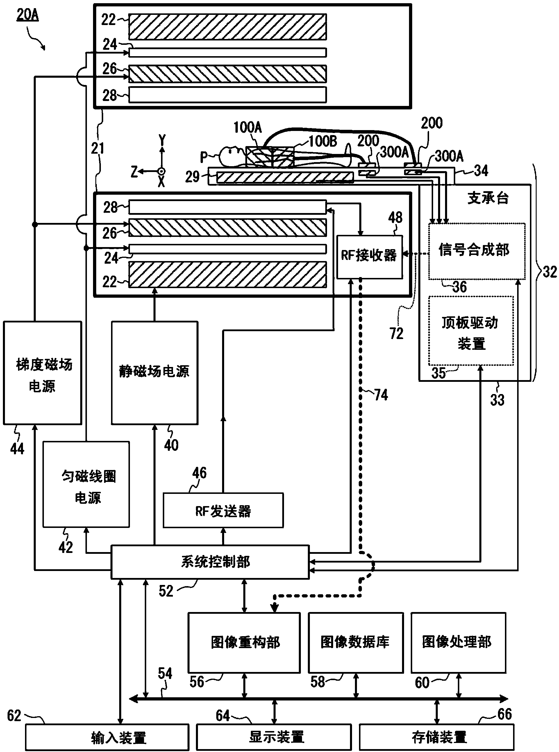
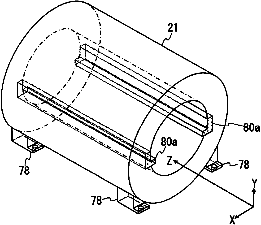
[0072] figure 1 It is a block diagram showing the overall configuration of the MRI apparatus 20A of the first embodiment. Such as figure 1 As shown, the MRI apparatus 20A has a gantry 21 and a bed apparatus 32 . The MRI apparatus 20A includes, for example, a static field magnet 22 , a shim coil 24 , a gradient magnetic field coil 26 , and a transmission RF coil 28 in a cylindrically formed gantry 21 . The stand 21 corresponds to a portion indicated by each thick rectangle in the figure.

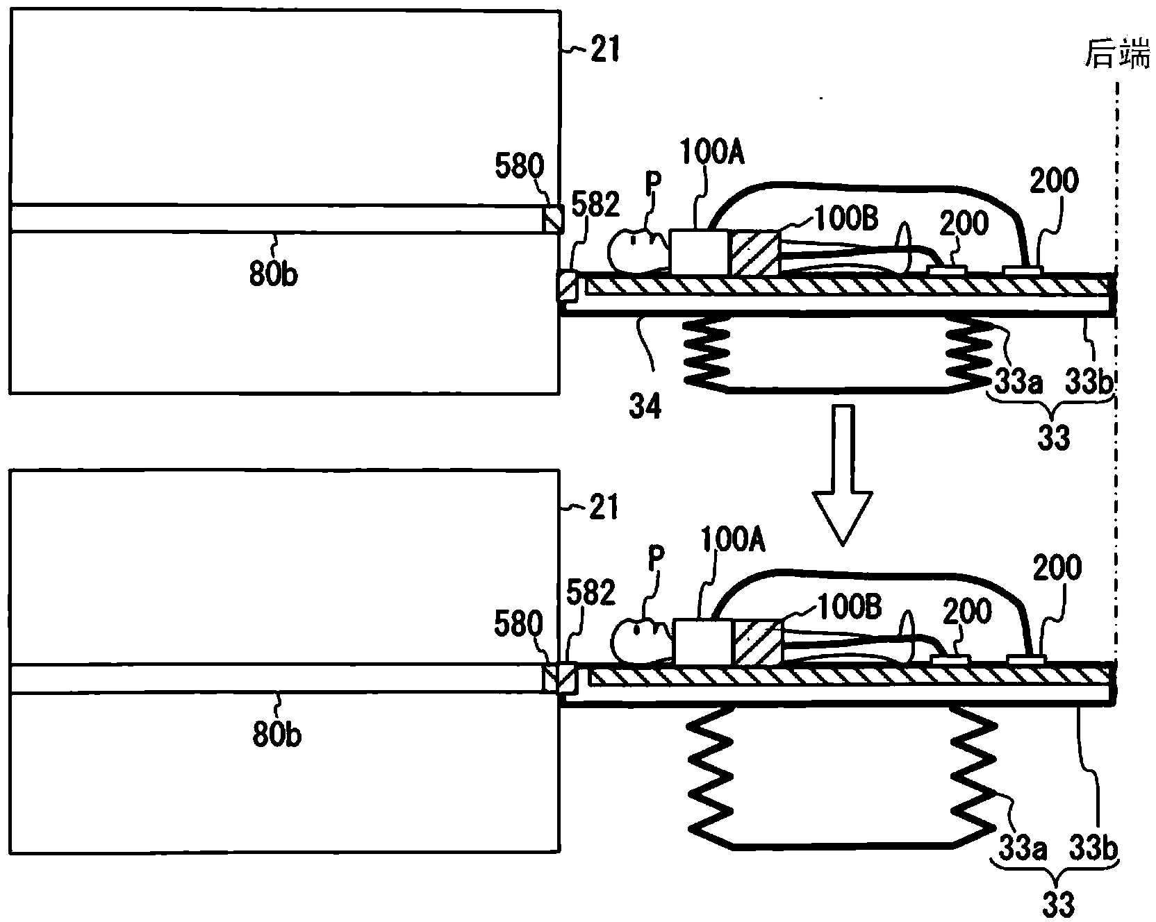
[0073] The bed device 32 has a support table 33 , a top board 34 , a top board driving device 35 , and a signal synthesis unit 36 ​​. The top plate 34 is movably supported on the support table 33 , and the subject P is placed on the top plate 34 . The top drive device 35 and the signal synthesis unit 36 ​​are arranged inside the support table 33 . The bed apparatus 32 may be of a type in which the position of the support table 33 is fixed within the imaging room, or may be of a movable d...

no. 2 approach

[0276] The MRI apparatus 20B of the second embodiment is capable of wirelessly transmitting electric power to the RF coil devices 100A and 100B even when the top plate 34 is inside the gantry 21 . The other functions are substantially the same as those of the first embodiment, so the description will focus on the differences from the first embodiment.

[0277] The overall block diagram of the MRI apparatus 20B is the same as that in the first embodiment figure 1 The configuration shown in is the same, so description is omitted. In addition, the schematic appearance structure of the gantry 21 and the bed device 32, the configuration of the RF coil devices 100A and 100B, and the arrangement and configuration of the fixing mechanism 500 are also similar to those in the Figure 2 ~ Figure 6 same as described in .

[0278] Figure 13 It is a schematic plan view of an X-Z plane of an apparatus coordinate system showing an arrangement example of the gantry-side charging unit 572 a...

no. 3 approach

[0392] In the third embodiment, among signals transmitted between the RF coil devices 100A, 100B and the control side (RF receiver 48 side) of the MRI apparatus 20C, signals other than the MR signal are passed through another induction electric field coupling type coupler. Send via in-track wiring. The aforementioned "signals other than MR signals" are, for example, control signals such as gate signals and reference signals, and signals of identification information of the RF coil devices 100A and 100B, and these signals are transmitted through electrical wiring. This has the effect of reducing the amount of signal converted into an optical signal.

[0393] The third embodiment is a modified example of the second embodiment, and is the same as the second embodiment except for the configuration to obtain the above-mentioned effects. Therefore, description will focus on parts that differ from the second embodiment, and descriptions of overlapping parts will be omitted.

[0394...


PUM


Abstract

The invention provides a magnetic resonance imaging apparatus and a bed device. The MRI apparatus of an embodiment comprises supports (80a-80c), first wireless communication units (200), second wireless communication units (300A-300C), and power supply units (320a, 320b, 550, 572, 574, 610). The supports support the tabletop inside the gantry. The first wireless communication units acquire the MR signals detected by the RF coil devices (100A, 100B) and wirelessly transmit the MR signals. The second wireless communication units receive the MR signals wirelessly transmitted from the first wireless communication units. By supplying power wirelessly to the first wireless communication units, the power supply units, at least a portion of which are disposed inside the bed device (32) or inside the supports, supply the power consumed by the RF coil devices through the first wireless communication units.

Description

technical field [0001] Embodiments of the present invention relate to a magnetic resonance imaging apparatus and a bed apparatus. Background technique [0002] MRI is an imaging method in which nuclear spins of a subject placed in a static magnetic field are magnetically excited by an RF pulse of a Larmor frequency, and an image is reconstructed from an MR signal accompanying the excitation. In addition, the above-mentioned MRI means magnetic resonance imaging (Magnetic Resonance Imaging), RF pulse means radio frequency pulse, and MR signal means nuclear magnetic resonance signal (nuclear magnetic resonance signal). [0003] Here, the RF coil device (Radio Frequency Coil Device), for example, transmits an RF pulse to the spins of atomic nuclei in the subject by flowing an RF pulse current through the coil, and detects the generated MR signal. As the RF coil device, there is an RF coil device built in the MRI device itself, but there is also an RF coil device that is recogni...

Claims


Application Information

Patent Timeline
Patent Type & Authority Applications(China)
IPC IPC(8): A61B5/055G01R33/34G01R33/36
CPCG01R33/3415G01R33/30G01R33/3614G01R33/3692
Inventor 富羽贞范
Owner TOSHIBA MEDICAL SYST CORP
Why Eureka
Try Eureka