
Methods for vacuum brazing, assembling and locating radio fuse antenna radiator

A positioning method and radiator technology, applied in the field of mechanical processing, can solve the problems of low assembly efficiency, low welding strength, easy creases and breakage, etc., to improve assembly efficiency, ensure electrical performance and parameters, and ensure welding quality Effect

Active Publication Date: 2012-10-10
GUIZHOU AEROSPACE ELECTRONICS TECH
View PDF5 Cites 6 Cited by
  • Summary
  • Abstract
  • Description
  • Claims
  • Application Information

AI Technical Summary

Problems solved by technology

The disadvantages are: (1) During assembly, the solder tabs are easily misplaced, requiring the cooperation of 2 people, and repeated operations are often required. Because the solder tabs are very brittle, they are prone to creases and breaks, resulting in the need to re-cut the solder tabs for assembly. It causes a waste of manpower and material resources. If the dislocation of the solder piece is not found, the solder will flow into the cavity after melting; (2) After the cover is installed, spot welding is used for positioning, and the solder joints are large, which affects the appearance and rough surface (3) The tightness between the cavity and the cover plate is uneven, which affects the uniformity and compactness of the solder filling, resulting in low welding strength and welding quality that does not meet the technical requirements; (4) If the size of the cover plate is out of alignment during assembly If the degree of grinding on both sides of the cover plate is different, the cracks on the cover plate will deviate, which will directly affect the electrical performance and electrical parameters of the radiator after welding; (5) The assembly efficiency of this method is low, and the average 41 minutes to assemble a set of radiators

Method used


Image

  • Methods for vacuum brazing, assembling and locating radio fuse antenna radiator
  • Methods for vacuum brazing, assembling and locating radio fuse antenna radiator
  • Methods for vacuum brazing, assembling and locating radio fuse antenna radiator

Examples


Embodiment Construction

[0019] The technical solution of the present invention is further described below in conjunction with the accompanying drawings, but the scope of protection is not limited to the description.

[0020] A vacuum brazing assembly positioning method for a radio fuze antenna radiator, the steps of which are as follows:

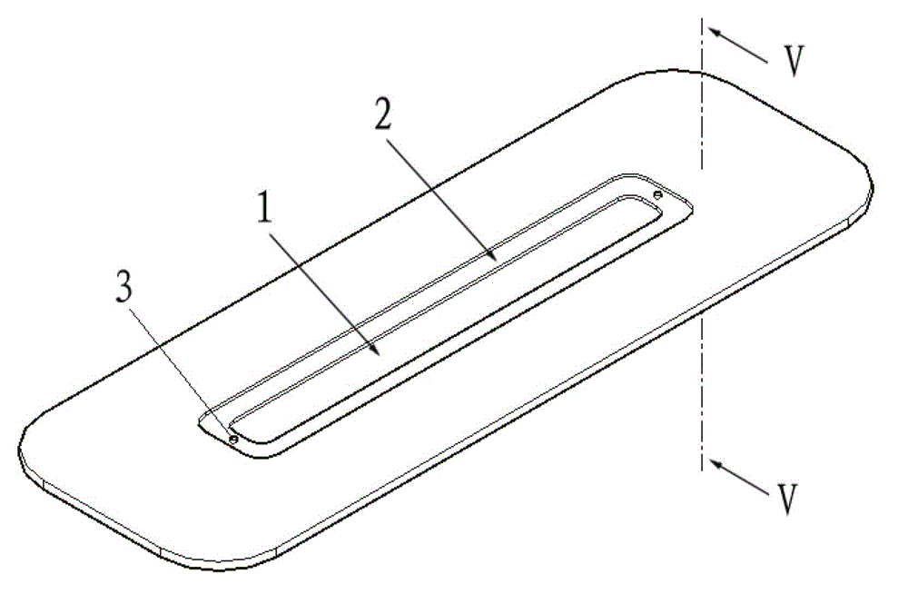
[0021] ①Use the positioning pin 3 for preliminary positioning;

[0022] ② At the welding seam 7 between the cover plate 4 and the cavity 1, use the burr positioning tool 8 to nail out the burr for precise positioning.

[0023] like Figure 1 to Figure 3 As shown, the positioning pins 3 are arranged at both ends of the welding step 2 .

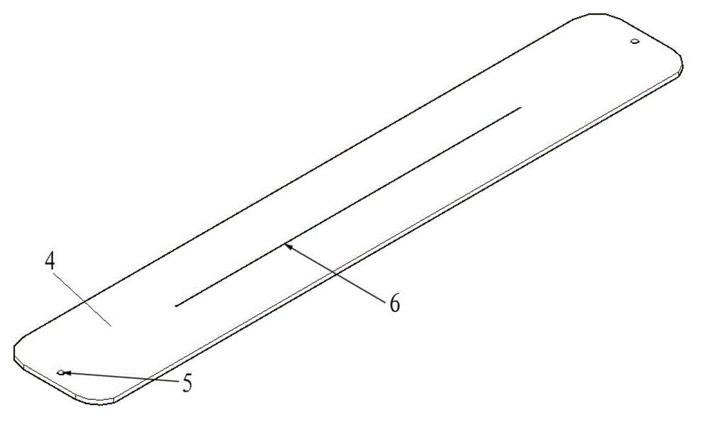
[0024] like Figure 4 As shown, a corresponding positioning hole 5 is provided on the cover plate 4 at a position corresponding to the positioning pin 3 . When assembling the cover plate 4, first install the welding piece on the welding step 2 of the cavity 1, and the two ends of the welding piece pass through the positioning pi...


PUM


Abstract

The invention discloses methods for vacuum brazing, assembling and locating a radio fuse antenna radiator, which comprise the following steps that (1) a locating pin is utilized to preliminarily locate; and (2) at the welding line of a cover plate and a cavity body, burrs are generated through the nailing of a burr positioning tool, so precision locating is carried out. The method for locating is utilized, a soldering flake can be well enabled not to dislocate during the assembling process, the seam in the cover plate is enabled not to deviate, and the molten soldering flux is enabled to uniformly and fully filled, and does not flow into the cavity. The cavity and the cover plate can be tightly, uniformly and smoothly fit with each other, accordingly, the welding strength, air tightness and surface appearance quality are well ensured, the electrical property is enabled to be qualified, and finally, the welding quality can be enabled to satisfy the requirements of technical conditions. The methods for assembling and locating are utilized, the consumption of manpower and material resources is reduced, and the average assembling time for each set is 33 minutes, so the assembling efficiency is improved.

Description

technical field [0001] The invention relates to a positioning method, in particular to a vacuum brazing assembly positioning method for a radio fuze antenna radiator, belonging to the field of mechanical processing. Background technique [0002] The radiator is an important component of the radio fuze antenna. It is connected with the cable to form a microwave transmission channel. The main function is to receive, transmit and transmit signals. Therefore, the welding quality of the radiator directly affects the electrical performance and parameters, and determines the accuracy of signal transmission. sex. [0003] The assembly and welding positioning method of the original process is: install the welding tab on the welding step, the size of the welding tab is consistent with the welding step, then install the cover plate, and use spot welding to position the weld seam between the cover plate and the cavity. The disadvantages are: (1) During assembly, the solder tabs are eas...

Claims


Application Information

Patent Timeline
IPC IPC(8): B23K3/08
Inventor 田叶青
Owner GUIZHOU AEROSPACE ELECTRONICS TECH
Learn More