
Method and machine for making brushes

A brush making machine and brush body technology, which is applied in the field of brush manufacturing, can solve the problems of limiting production speed, reducing the number of revolutions, and consuming time, and achieves the effect of reliable brush production and reduced vibration

Active Publication Date: 2017-01-04
ZAHORANSKY AG
View PDF5 Cites 0 Cited by
  • Summary
  • Abstract
  • Description
  • Claims
  • Application Information

AI Technical Summary

Problems solved by technology

[0006] It is currently only possible to reduce the number of revolutions for the entire processing cycle of the brush with a corresponding safety factor, which strongly limits the production speed
Different speeds can be adjusted manually in the individual processing sections if necessary, but this is time-consuming

Method used


Image

  • Method and machine for making brushes
  • Method and machine for making brushes
  • Method and machine for making brushes

Examples


Embodiment Construction

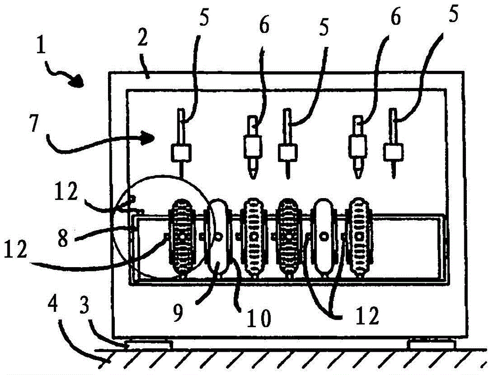
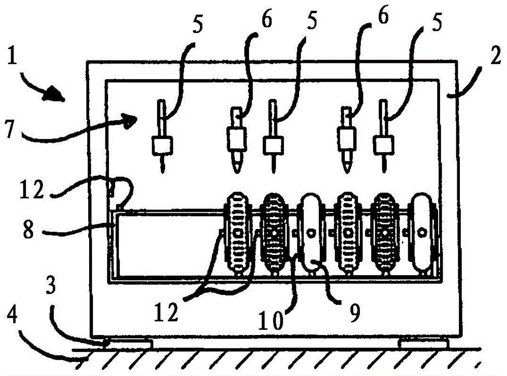
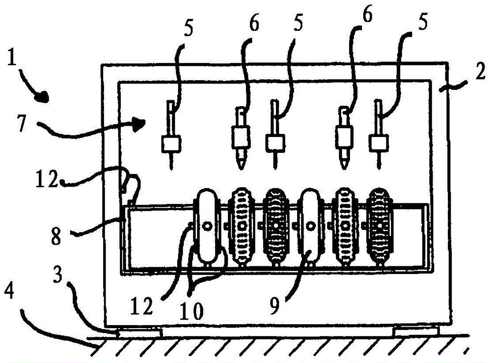
[0043] A whole brush machine marked with 1 is in accordance with Figure 1 to 3 There is a machine housing 2 which stands on the floor 4 with parking feet 3.

[0044] The brush making machine 1 has three drilling tools 5 and two caulking tools 6 as processing tools 7, and these processing tools are arranged alternately side by side.

[0045] Below the processing tool 7 there is a holding and positioning device 8 which is only shown schematically for the brush body 9 to be processed. Each brush body 9 is held in a brush tensioning device 10 ( Figure 4 ) And can be positioned in front of one of the processing tools 7 by means of the holding and positioning device 8. Here, the holding and positioning device 8 is used to move the brush body 9 from the drilling tool 5 toward the stuffing tool 6 on the one hand, and on the other hand to position the brush body 9 next to the corresponding processing tool 7 in order to move the brush body 9 All the drilling or packing positions on 9 are ...


PUM


Abstract

The invention relates to a method for manufacturing a brush, in which bundle receiving holes (11) are drilled into the brush body (9) and / or bristle bundles are packed into the bundle receiving holes of the brush body; in a first measuring process The processing tool (7) is driven at a predetermined number of revolutions. The vibrations occurring on the brush machine (1) during drilling or filling are measured at several processing positions (13) and compared with the permissible maximum value. If the maximum value is exceeded at a machining position, the number of revolutions (n) of the machining tool is reduced at the corresponding machining position in the subsequent measuring process or if the maximum value is lower than the maximum value at a machining position, in the subsequent measuring process at the corresponding machining position Increase the number of revolutions of the processing tool. The corresponding modified rotational speed values ​​are stored at each machining position and so many measuring processes are carried out until the maximum value is dropped below at all machining positions. After the measuring process, the production process is executed with the rotational speed values ​​determined and stored during the measuring process. The invention also relates to a brush making machine.

Description

Technical field [0001] The invention relates to a method for manufacturing a brush. The invention also relates to a brush making machine. Background technique [0002] In order to produce as many brushes as possible per unit time, the machine revolutions of the brush making machine can be increased. Here, the possible number of drilling or packing processes per minute is defined as the number of machine revolutions. The speed of 500 rpm means that 500 beam receiving holes can be drilled or filled per minute. [0003] But a higher number of revolutions also means greater vibration on the brush machine. When these vibrations are too large, they may result in enlarged beam receiving holes or even elongated holes when drilling. The bit may even break due to lateral forces. During packing, excessive vibration may cause the anchoring to be not performed centrally in the bundle receiving hole, which may cause the packing tongue to break or the bristle bundle to fall. It is also poss...

Claims


Application Information

Patent Timeline
Patent Type & Authority Patents(China)
IPC IPC(8): A46D3/06
CPCA46D3/00A46D3/06A46D3/02
Inventor T·默腾S·策依赫尔
Owner ZAHORANSKY AG
Learn More