U-shape Furnace Tube Bending Process Using Fixture Locking Rail Mechanism and Fixture Position Sensor

A furnace tube bending and sensor technology is applied in the field of manufacturing furnace tubes of a heating furnace, which can solve the problems of low shape accuracy, long processing process, uneven processing deformation, etc., and achieve the effect of continuous bending process and small processing space.

Active Publication Date: 2016-01-20
郎溪品旭科技发展有限公司
View PDF5 Cites 0 Cited by
  • Summary
  • Abstract
  • Description
  • Claims
  • Application Information

AI Technical Summary

Problems solved by technology

[0005] The invention is a U-shaped heating furnace tube bending process, which aims to solve the defects of uneven processing deformation, long processing process, and low shape precision in the prior art, and provides a bending process of a heating furnace tube with a specific shape. craft

Method used


Image

  • U-shape Furnace Tube Bending Process Using Fixture Locking Rail Mechanism and Fixture Position Sensor
  • U-shape Furnace Tube Bending Process Using Fixture Locking Rail Mechanism and Fixture Position Sensor
  • U-shape Furnace Tube Bending Process Using Fixture Locking Rail Mechanism and Fixture Position Sensor

Examples


Embodiment Construction

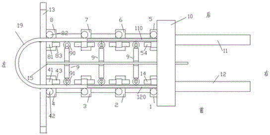
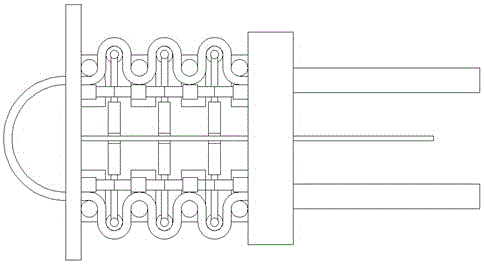
[0028] Attached below Figure 1-3 The present invention will be described in detail.

[0029] The U-shaped furnace tube bending process using the clamp rail mechanism and the clamp position sensing sensor uses a furnace tube bending device. The U-shaped furnace tube bending device includes a left frame 13 and a pushing mechanism 10. The pushing mechanism 10 is in the On the left side of the left frame 13, a guide rod 15 is fixedly arranged at the middle position on the right side of the left frame 13, and the guide rod 15 extends horizontally in the left-right direction, and the left end of the guide rod 15 is fixed to the left frame 13. Connected, the right end of the guide rod 15 is slidingly connected with the middle part of the pushing mechanism 10, and the left frame 13 is provided with a channel for the original U-shaped furnace tube to be loaded and passed through and for the processed furnace tube to be unloaded. ; On the guide rod 15, three bending hydraulic devices ...


PUM


Abstract

The invention discloses a U-shaped heating furnace tube bending technology which uses furnace tube bending equipment. The furnace tube bending equipment comprises a left machine frame and a pushing and pressing mechanism, wherein the pushing and pressing mechanism is located on the right side of the left machine frame, a guide rod is fixedly arranged in the middle of the right side of the left machine frame and extends horizontally in the left-right direction, the left end of the guide rod is fixedly connected with the left machine frame, the right end of the guide rod is connected with the middle of the pushing and pressing mechanism in a sliding mode, a channel used for allowing an original U-shaped furnace tube to pass through to be fed and a well machined furnace tube to pass through to be discharged is formed in the left machine frame, and three bending hydraulic devices are arranged on the guide rod and between the left machine frame and the pushing and pressing mechanism in a sliding mode in sequence from left to right.

Description

technical field [0001] This application relates to the manufacture of heating furnace tubes, specifically a U-shaped heating furnace tube bending process. Background technique [0002] Heating furnaces are widely used in industry, such as billet heating, workpiece heat treatment, etc. In order to increase the heating uniformity of the heating furnace, the furnace tube is often bent. [0003] In the prior art, in order to ensure the requirements for the specific shape of the heating furnace and meet the respective requirements for the specific heating heat, it is usually necessary to bend the shape of the furnace tube in a specific shape. For the bending of the furnace tube of the heating furnace, stamping is often used in the prior art. This forming method can efficiently and quickly realize bending processing, has high processing precision and low cost, and is widely used in the prior art. However, this heating method is easy to produce a large amount of uneven deformati...

Claims


Application Information

Patent Timeline
Patent Type & Authority Patents(China)
IPC IPC(8): B21D11/07
Inventor 舒丽燕
Owner 郎溪品旭科技发展有限公司
Why Eureka
Try Eureka