Support arm for reflector of paraboloid trough condenser

A technology of a condenser and a mirror, which is applied to the field of a condenser mirror support arm, can solve the problems that the size and shape accuracy of the support arm cannot be satisfied, the weight of the support arm is reduced, and the investment in the mold is large, etc., and achieves high shape and dimensional accuracy. Effect

Inactive Publication Date: 2012-11-21
INST OF ELECTRICAL ENG CHINESE ACAD OF SCI
View PDF6 Cites 11 Cited by
  • Summary
  • Abstract
  • Description
  • Claims
  • Application Information

AI Technical Summary

Problems solved by technology

[0006] In the trough solar power plants that have been built, the models of trough collectors that have been used are LS-2, LS-3, EUROTROUGH, etc., and the mirror arms of these parabolic trough concentrators are made of square steel pipes or rectangular The steel pipe is welded, the welding speed is slow, and the cost is high; due to the welding stress, the support arm is prone to deformation after hot-dip galvanizing, and the size and shape accuracy of the support arm are difficult to meet
[0007] The Chinese patent with the publication number CN 101305247A discloses a support arm for a columnar parabolic collector. The arm is stamped from a steel plate of 1 to 2 mm. Due to the large size of the arm, the focal length commonly used in the world is 1.71 The size of the parabolic trough concentrator with an opening of 5.76 meters is generally about 2.5 meters. The parabolic trough concentrator with a larger opening is the current development direction of the parabolic trough concentrator in the world. The size will be larger, so the use of stamping technology to manufacture the support arm requires a large and expensive stamping die, and the investment in the die is large, which is not conducive to reducing the manufacturing cost of the support arm;
[0008] The support arm is formed by pressing at least one plate, and the mesh-shaped ribs are pressed on the plate to

Method used


Image

  • Support arm for reflector of paraboloid trough condenser
  • Support arm for reflector of paraboloid trough condenser
  • Support arm for reflector of paraboloid trough condenser

Examples


Embodiment Construction

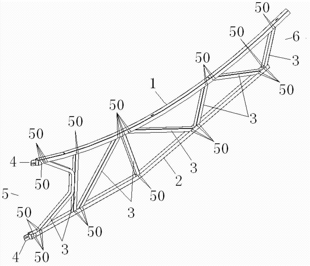
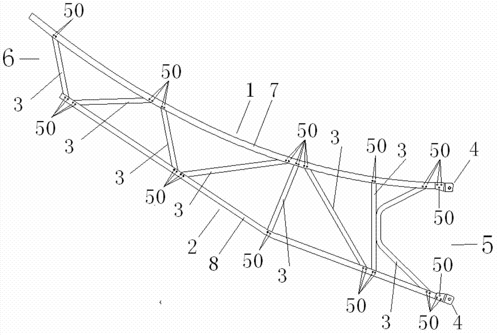
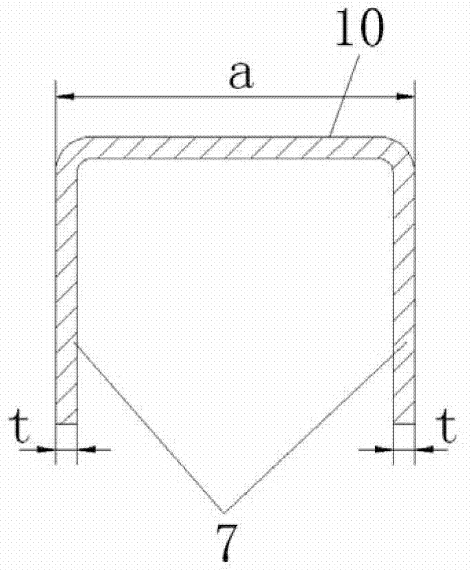
[0036] Such as figure 1 As shown, the reflector arm of the parabolic trough concentrator is composed of an upper chord 1 , a lower chord 2 , a web 3 and a connecting piece 4 . The upper chord 1, the lower chord 2, and the web 3 are metal thin-walled parts with a U-shaped cross-section processed from cold-rolled thin steel plates. The upper chord 1 is located at the top of the arm, and the section of the upper chord 1 is as follows: image 3 shown. The lower chord 2 is located at the bottom of the arm, and the section of the lower chord 2 is as follows: Figure 4 As shown, the cross-sectional size of the lower chord 2 is the same as that of the upper chord 1. The section of the web bar 3 is as Figure 5 As shown, the section width of the web 3 is c=a-2t=b-2t, so that the web 3 can be inserted into the U-shaped grooves of the upper chord 1 and the lower chord 2 . Eight webs 3 are located between the upper chord and the lower chord, and are arranged along the length directio...


PUM


Abstract

The invention discloses a support arm for a reflector of a paraboloid trough condenser. The support arm for the reflector of the paraboloid trough condenser comprises a top boom (1), a lower boom (2), web members (3) and connecting pieces (4). The top boom (1), the lower boom (2) and the web members (3) are metal thin-wall parts of which the cross sections are non-closed. The top boom (1) of which the surface is treated is bent into a curve shape or a broken line shape; the top boom (1) is suitable for installing at least one parabolic cylinder reflector sub-mirror (20) in shape; the web members (3) of which the surfaces are treated are located between the top boom (1) and the lower boom (2) of which the surface is treated and are connected with the top boom (1) and the lower boom (2) in the manner of riveting without rivets to form the certain-strength and certain-rigidity support arm of a plane girder structure; the connecting pieces (4) are connected with the end parts of the top boom (1) and the lower boom (2) at the first end (5) of the support arm in the manner of riveting without rivets; and the support arm is connected with a central girder (60) through the connecting pieces (4).

Description

technical field [0001] The invention relates to a concentrator reflector support arm of solar thermal power generation equipment. Background technique [0002] The parabolic trough concentrator is used as a collection device for solar radiation energy. It is used in conjunction with the heat absorbing tube to form a parabolic trough collector, which can provide heat for solar thermal power generation, solar desalination of sea water, solar air conditioning, industrial production, etc. [0003] Most parabolic trough solar concentrators are formed by installing multiple parabolic cylindrical reflector mirrors on the support structure of the parabolic trough concentrator, and assembling them into a whole parabolic cylindrical reflector with appropriate precision. The support structure supports and ensures the stability of the overall parabolic cylinder. [0004] At present, there are mainly two types of support structures for parabolic trough concentrators: one is the space tr...

Claims


Application Information

Patent Timeline
IPC IPC(8): F24J2/52
CPCY02E10/47
Inventor 付向东王志峰
Owner INST OF ELECTRICAL ENG CHINESE ACAD OF SCI
Why Eureka
Try Eureka