Composite mold for integrally molding inner profile of ribbed composite wall panel

A composite material and integral molding technology, which is applied in the field of composite molds for integrally forming the inner surface of reinforced composite wall panels, can solve problems affecting the internal quality or assembly of components, insufficient rigidity of rubber soft molds, and dense pores in the R corner area, etc. , to achieve the effect of increasing stiffness, avoiding frequent repairs, and avoiding dense pores

Active Publication Date: 2017-01-11
AVIC COMPOSITES
View PDF5 Cites 10 Cited by
  • Summary
  • Abstract
  • Description
  • Claims
  • Application Information

AI Technical Summary

Problems solved by technology

At present, the R corners of the inner surface soft molds of various types of reinforced wall panels are mostly made of flexible materials such as Airpad rubber. Due to the insufficient rigidity of the rubber soft molds, during the curing and molding process of the components, the R corners are easily caused by insufficient pressure. Defects such as dense pores, delamination, resin accumulation, fiber folds, shape deviation, etc., which affect the internal quality or assembly of components

Method used


Image

  • Composite mold for integrally molding inner profile of ribbed composite wall panel
  • Composite mold for integrally molding inner profile of ribbed composite wall panel
  • Composite mold for integrally molding inner profile of ribbed composite wall panel

Examples


Embodiment 1

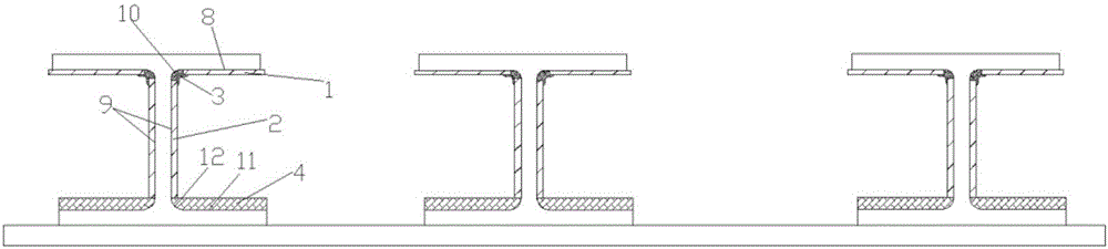
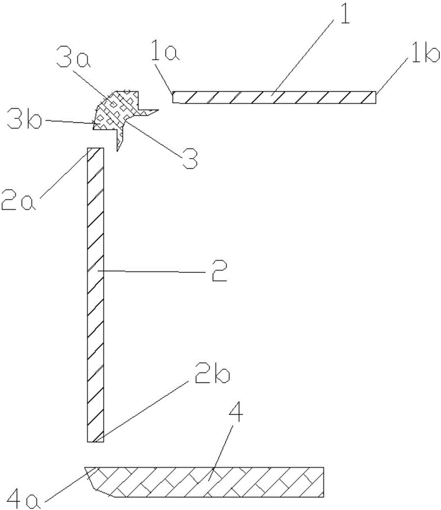
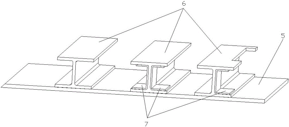
[0029] Embodiment 1: The external dimensions of the "I" type reinforced wall panel are 2500 mm × 2500 × 240 mm (length × width × height), and the skin 5 is longitudinally equipped with 3 reinforcements 6 with an "I" type cross section. The dimensions of the upper and lower R angles are both R5, which are integrally formed by RFI technology, such as image 3 shown. The inner profile of the rib is assembled with the U-shaped metal part 7 in some areas, so the lower profile of the upper flange of the rib is 8, the inner profile of the web of the rib is 9, the inner profile of the R angle of the upper rib is 10, and the lower profile of the rib is The surface accuracy of the upper profile 11 of the flange and the inner profile 12 of the R angle under the rib must be controlled within a certain deviation range to meet the assembly requirements. Here we adopt the mold solution of the present invention.

[0030]a "I" type rib upper flange lower profile 8 and rib web inner profile 9 ...

Embodiment 2

[0035] Example 2: "J" type reinforced panel structure such as Figure 7 , "J"-shaped reinforced wall panels have an overall dimension of 2000mm×1500×140mm (length×width×height), and there are three reinforcements 6 with a "J"-shaped section in the longitudinal direction on the upper skin 5, and the upper and lower ribs The size of the R angle is R3, and it is integrally formed by RFI technology. The ribs are opened in the web area, and the U-shaped metal parts 7 corresponding to the openings should be assembled to the inner profile of the "J" rib, so the lower profile of the upper flange of the rib is 8, and the inner profile of the web of the rib is 9 1. The surface accuracy of the inner profile surface 10 of the R angle on the rib, the upper profile surface 11 of the lower flange of the rib and the inner profile surface 12 of the R angle under the rib must be precisely controlled to ensure the compatibility with the outer profile of the U-shaped metal part 7 Assembly coordi...

Embodiment 3

[0040] Example 3: "C" type reinforced panel structure such as Figure 9 , "C" type reinforced wall panel dimensions are 2000mm × 800 × 100mm (length × width × height), the skin 5 is longitudinally equipped with 3 reinforcements 6 with a cross-section of "C" type, and the R angle on the ribs The dimension is R5, and the dimension of the lower R angle is R3. The lower flange of the rib and the skin are interlayer reinforced by stitching, and are integrally formed by RFI technology. The two outer ribs are opened in the web area, and the U-shaped metal parts 7 corresponding to the openings must be assembled in the opening area of ​​​​the inner surface of the "C"-shaped rib. In order to ensure the forming quality and assembly of the "C"-shaped rib Requirement, here we still adopt the mold scheme of the present invention.

[0041] a "C" shaped rib upper flange lower profile 8 and rib web inner profile 9 are planar structures, choose 2mm thick aluminum plate to process upper flange ...


PUM

PropertyMeasurementUnit
thicknessaaaaaaaaaa
thicknessaaaaaaaaaa

Abstract

The invention belongs to the polymer matrix composite molding technology, and relates to a composite mold for integrally molding an inner profile of a ribbed composite wall panel. The molding mold comprises an upper flange molding soft mold body, a web molding soft mold body, an upper R corner molding soft mold body and a lower flange and R corner molding soft mold body. The upper R corner molding soft mold body of the composite mold is made of a rigid and flexible blended and cured material, and therefore the rigidity of a soft mold upper R corner area is increased, the pressure in a tank is better transmitted to an upper R corner area of the ribbed composite wall panel, and the defects of upper R corner area hole concentration, layering, appearance deviation and the like can be effectively avoided. The lower flange and R corner molding soft mold body is utilized for guaranteeing the inner quality and appearance accuracy of a lower flange and a lower R corner area, especially a side profile of the lower flange and R corner molding soft mold body is chamfered according to the theoretical appearance of an inner profile of a lower R corner of each rib, the procedure of preparing a lower R corner molding soft mold body by entering the tank is omitted, the mold manufacturing cost is reduced, and the appearance accuracy of the lower R corner area is improved.

Description

technical field [0001] The invention belongs to polymer-based composite material molding technology, and relates to a composite mold for integrally molding the inner surface of a reinforced composite material wall plate. Background technique [0002] With its advantages of high specific strength, high specific stiffness and strong designability, polymer matrix composites have been widely used in the main load-bearing and secondary load-bearing components of aircraft, such as wings, fuselages, doors, etc. Wait. All kinds of load-bearing components, especially large-scale load-bearing components, mostly adopt the structural form of combining skin and various tendons. [0003] Due to the development of advanced technology such as liquid forming, reinforced composite wall panels can be integrally formed, and have been applied in many aircraft components. In the overall molding process, the use of a fully rigid mold is likely to cause insufficient pressure in the R angle or oth...

Claims


Application Information

Patent Timeline
Patent Type & Authority Applications(China)
IPC IPC(8): B29C33/38
CPCB29C33/3828
Inventor 王海雷高艳秋
Owner AVIC COMPOSITES
Why Eureka
Try Eureka