Automatic assembly method of decorative light production line

An automatic assembly and production line technology, applied in the field of machinery, can solve problems such as increased useless workload, time-consuming production, and decreased accuracy, and achieve the effects of improving production efficiency, reducing production costs, and ensuring the pass rate

Active Publication Date: 2014-06-18
平湖市博宏塑料制品厂
View PDF7 Cites 12 Cited by
  • Summary
  • Abstract
  • Description
  • Claims
  • Application Information

AI Technical Summary

Problems solved by technology

[0003] In traditional production and processing, the bulbs are usually manually assembled and configured by hand, so that the assembly of the filaments in each bulb cannot form a standardized unified positioning, resulting in a decrease in accuracy. The alignment deviation of individual light bulbs leads to disconnection or virtual connection, which makes the quality of the entire series-connected light chain unqualified and causes serious economic losses.
At the same time, the production method of manual processing cannot detect bulbs that do not light up due to damaged filaments during the assembly process, so the damaged bulbs are still installed with lamp caps, resulting in an increase in useless workload, and damaged bulbs are confused with good bulbs Entering the next processing procedure will continue to affect the pass rate of finished products and reduce economic benefits
Manual assembly also has problems such as a large amount of labor, time-consuming production, low efficiency, increased production costs, and weakened market competitiveness.

Method used


Image

  • Automatic assembly method of decorative light production line
  • Automatic assembly method of decorative light production line
  • Automatic assembly method of decorative light production line

Examples


Embodiment Construction

[0037] The following are specific embodiments of the present invention and in conjunction with the accompanying drawings, the technical solutions of the present invention are further described, but the present invention is not limited to these embodiments.

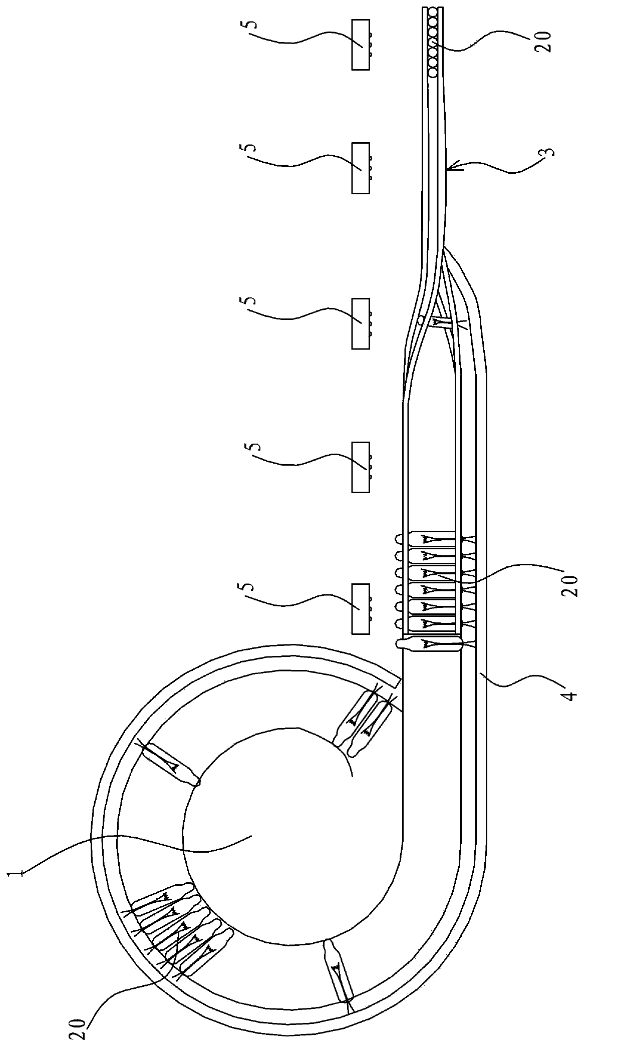
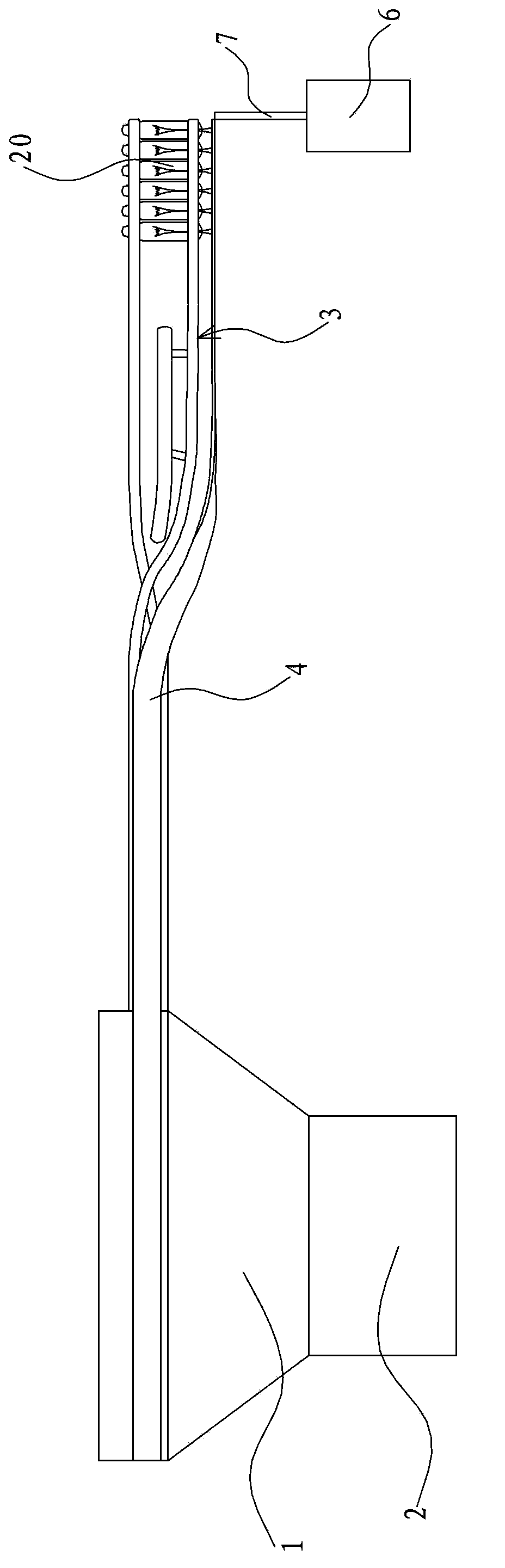
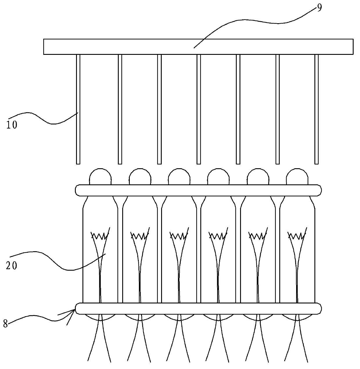
[0038] Such as Figure 1 to Figure 9 As shown in , the automatic assembly device of this decorative lamp production line includes a shaking tray 1, a vibrator 2, a feeding track 3, a conveying track 8, a batching track 16, a positioning mechanism, a wire clamping mechanism, a branching mechanism, a testing mechanism, Discharging mechanism, seating mechanism and wire folding mechanism, etc.

[0039] The bottom of the shaking tray 1 has a disc-shaped collecting cavity, and has an upward feeding opening, and is provided with a circle that connects the collecting cavity and gradually rises around the arc. The side edge extends horizontally to form a discharge port, and the discharge port connects with the feed port of the fee...


PUM


Abstract

The invention provides an automatic assembly method of a decorative light production line. The automatic assembly method of the decorative light production line can solves the problems of poor precision, low production efficiency and the like in existing decorative light production and comprises a vibrating tray, a vibrator, a feeding rail, a conveying rail, a blending rail, a positioning mechanism, a filament clamping mechanism, a forking mechanism, a testing mechanism, a discharging mechanism, a holder assembling mechanism and a filament bending mechanism. The automatic assembly method comprises the following steps of 1) material feeding; 2) vibrating arrangement; 3) horizontal conveying; 4) torsional transition conveying; 5) vertical conveying; 6) inter-insertion positioning; 7) filament clamping; 8) forking; 9) testing; 10) discharging; 11) holder assembling; 12) filament bending; 13) finish product collection. The automatic assembly method of the decorative light production line achieves mechanical fully-automatic assembly through the cooperation of an automatic feeding device and an automatic assembly device and has the advantages of improving the production efficiency, ensuring the percentage of pass, reducing the production cost and the like.

Description

technical field [0001] The invention belongs to the technical field of machinery, and relates to a production line step, in particular to an automatic assembly method for a decorative lamp production line. Background technique [0002] Christmas decorative lanterns are commonly known as Lala bubbles, which include a transparent shell, a filament is set inside the transparent shell, and the filament extends from the bottom of the transparent shell to the lamp foot, and the bottom of the transparent shell is set with a lamp cap. Form the filament into a locating assembly. Subsequently, a large number of single bulbs are connected in series through wires to complete the finished product of the overall Christmas decorative lantern. [0003] In traditional production and processing, the bulbs are usually manually assembled and configured by hand, so that the assembly of the filaments in each bulb cannot form a standardized unified positioning, resulting in a decrease in accuracy...

Claims


Application Information

Patent Timeline
Patent Type & Authority Applications(China)
IPC IPC(8): B23P21/00B65G47/24
CPCB23P21/00B65G47/24
Inventor 王平平
Owner 平湖市博宏塑料制品厂
Why Eureka
Try Eureka