A clamp used to support the main bolt of the pressure vessel

A technology for supporting pressure and main bolts, applied in the direction of manufacturing tools, workpiece clamping devices, etc., can solve problems such as easy dumping, personnel and equipment damage, and achieve the effect of avoiding dumping accidents and protecting personnel.

Active Publication Date: 2016-03-02
RES INST OF NUCLEAR POWER OPERATION +1
View PDF6 Cites 0 Cited by
  • Summary
  • Abstract
  • Description
  • Claims
  • Application Information

AI Technical Summary

Problems solved by technology

However, the heavy dead main bolt is prone to tipping over during the cutting process or when the cutting is completed, thereby causing injury to personnel and equipment

Method used


Image

  • A clamp used to support the main bolt of the pressure vessel
  • A clamp used to support the main bolt of the pressure vessel
  • A clamp used to support the main bolt of the pressure vessel

Examples


Embodiment 1

[0024] For the working condition (1) the bolts on the adjacent sides of the main bolt 1 to be cut to death have not been killed, and have been successfully removed.

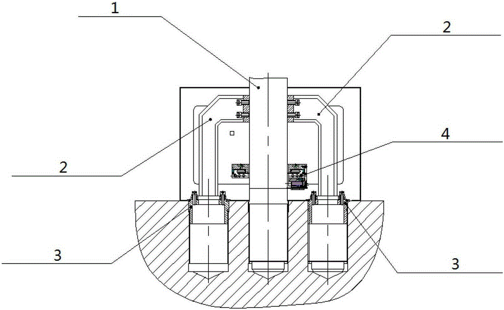
[0025] Such as figure 1 As shown, the left and right clamps include: screw sleeve 3 and inverted Shaped fixture body 2. The screw sleeve 3 is a cylinder with a closed upper end, and its side wall is provided with threads, and the screw sleeve 3 is screwed into the screw holes on both sides of the adjacent main bolt for positioning; the inverted Shaped clamp body 2, one end of which is fixed on the part where the main bolt protrudes from the flange surface of the pressure vessel through a fixing component such as a screw, and the other end is fixed on the part that is screwed into the screw holes on both adjacent sides through a fixing component such as a screw or a flange. On the screw sleeve 3. upside down The contact surface between the clamp body 2 and the main bolt 1 to be cut and killed is an arc-shap...

Embodiment 2

[0027] For the working condition (2), there are dead bolts adjacent to the bolts on both sides of the main bolt 1 to be cut and dead, and the adjacent dead bolts have not been cut.

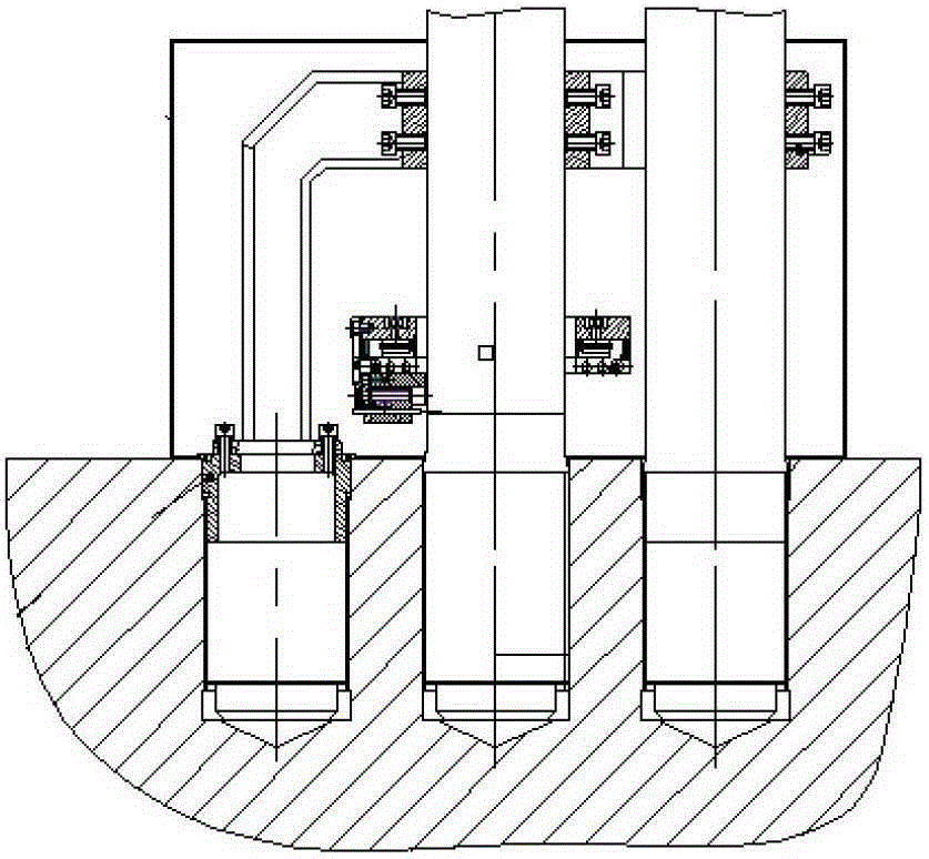
[0028] Such as figure 2 As shown on the right side, on the side of the dead bolt adjacent to the dead main bolt 1 to be cut, the following type of fixture is used: the fixture consists of two components: component one is connected by two arc-shaped clips facing back and The second component is an independent arc-shaped clamp. An arc-shaped clamp of component one is placed on the side wall of the main bolt 1 to be cut and killed, and is fastened with the clamp on the other side of the main bolt 1 to be cut and killed by screws. The other arc-shaped clamp of component one The hoop is placed on the side wall of the dead bolt adjacent to the main bolt 1 to be cut, and it is fastened with the component two on the other side of the dead bolt by screws.

Embodiment 3

[0030] For the working condition (3), there are dead bolts adjacent to the bolts on both sides of the main bolt 1 to be cut and dead, and the adjacent dead bolts have been cut off, leaving only a short part protruding from the flange surface of the pressure vessel.

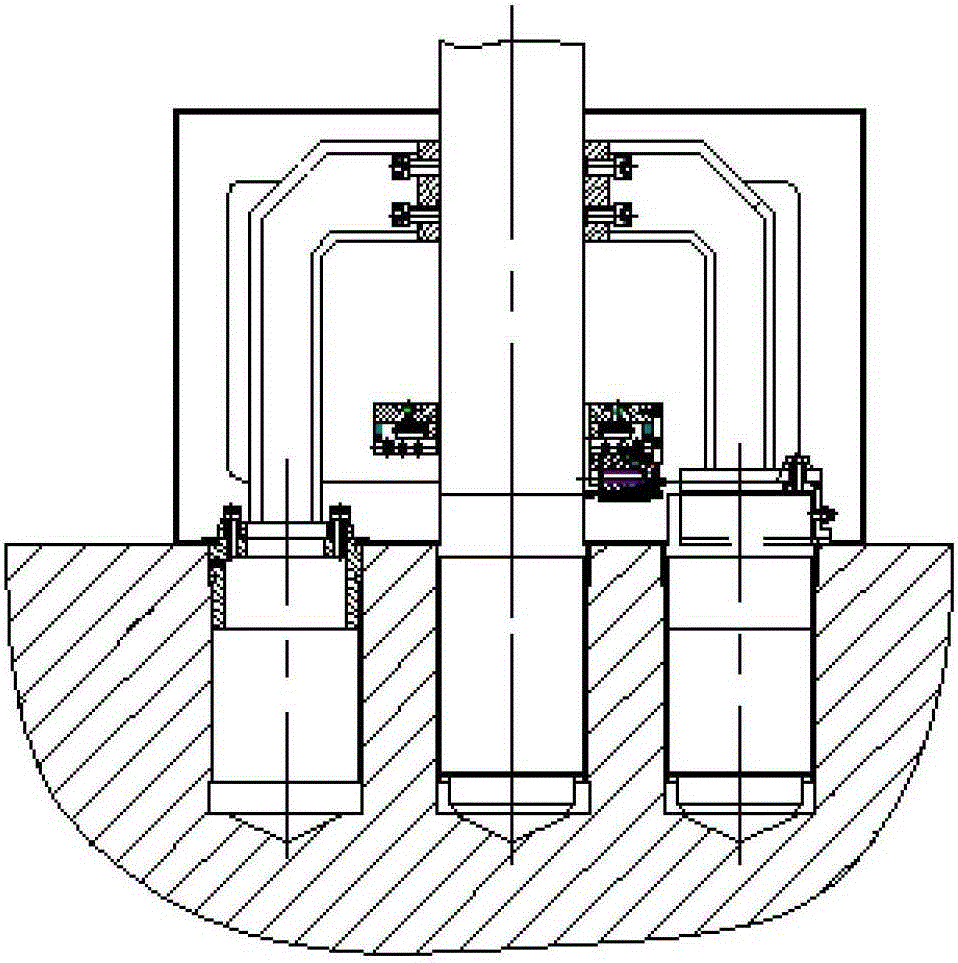
[0031] Such as image 3 As shown on the right, on the side where there is a dead bolt adjacent to the dead main bolt 1 to be cut, the following types of clamps are used: round sleeve and inverted Shaped fixture body 2. The circular sleeve is a cylinder with a sealed upper end and an open lower end, which is placed over the cut-off bolt on this side for positioning; the inverted Shaped fixture body 2, one end of which is fixed on the part where the main bolt is stuck and protrudes from the flange surface of the pressure vessel through a fixing component such as a screw, and the other end is fixed on the round sleeve. upside down The contact surface between the clamp body 2 and the main bolt 1 to be cut and ki...


PUM


Abstract

The invention belongs to the technical field of nuclear power overhauling equipment, and particularly relates to a fixture for supporting seized main bolts of a pressure container. The fixture comprises bolt sleeves and inverted L-shaped fixture bodies, wherein the bolt sleeves are respectively in the shape of a cylinder of which the upper end face is closed; the bolt sleeves are respectively rotated into bolt holes adjacent to the seized main bolts for positioning; one end of each of the inverted L-shaped fixture bodies is fixedly arranged on a part, stretching out of the flange face of the pressure container, of the corresponding seized main bolt; the other end of each of the inverted L-shaped fixture bodies is fixedly on the corresponding bolt sleeve screwed into the bolt hole; contact faces between the inverted L-shaped fixture bodies and the corresponding to-be-cut seized main bolts are respectively a circular arc type hoop matched with the dimensions of the side wall of the main bolt; each of the contact faces is fastened with the fixture on the other side of the corresponding to-be-cut seized main bolt. According to the fixture, as each of the seized main bolts is supported and fixed in a way of being clamped on two sides, a collapse accident occurring in the course of cutting or at the end of cutting the seized main bolts of the pressure container is effectively avoided; therefore the safety of people and equipment is guaranteed.

Description

technical field [0001] The invention belongs to the technical field of nuclear power maintenance equipment, and in particular relates to a clamp for supporting a pressure vessel to kill a main bolt. Background technique [0002] In some cases, the main bolts of the pressure vessel of the nuclear power plant will be seized and cannot be screwed in or out. If they are forced to rotate, the screw holes of the main bolts of the pressure vessel will be damaged or even severely damaged, resulting in irreversible serious accidents. [0003] In the prior art, the technical solution of boring and milling is used to cut and remove the seized main bolts in the pressure vessel. To facilitate boring and milling, the seized main bolt needs to be cut before the boring and milling operation. However, the heavy dead main bolt is prone to toppling during the cutting process or when the cutting is completed, thus causing injury to personnel and equipment. Contents of the invention [0004]...

Claims


Application Information

Patent Timeline
Patent Type & Authority Patents(China)
IPC IPC(8): B25B11/00
CPCB25B11/00
Inventor 周淼周政李彦宾卢冰张高剑
Owner RES INST OF NUCLEAR POWER OPERATION
Why Eureka
Try Eureka