Shaft-end deslagging spiral conveyer

A technology of screw conveyor and shaft end, applied in the field of screw slag discharge device, can solve the problems of difficult control of soil bin pressure, unfavorable belt conveyor transportation, tunnel construction progress and safety impact, etc.

Active Publication Date: 2014-06-18
辽宁三三工业有限公司
View PDF4 Cites 10 Cited by
  • Summary
  • Abstract
  • Description
  • Claims
  • Application Information

AI Technical Summary

Problems solved by technology

Although the existing technology can realize the screw slag discharge function, because the shaft end drive is used, the drive system directly drives the screw rod. Obviously, the torque increases, and the screw rod is supported at one end, which is easy to be eccentrically worn with the cylinder, which changes the slag

Method used


Image

  • Shaft-end deslagging spiral conveyer
  • Shaft-end deslagging spiral conveyer

Examples


Embodiment Construction

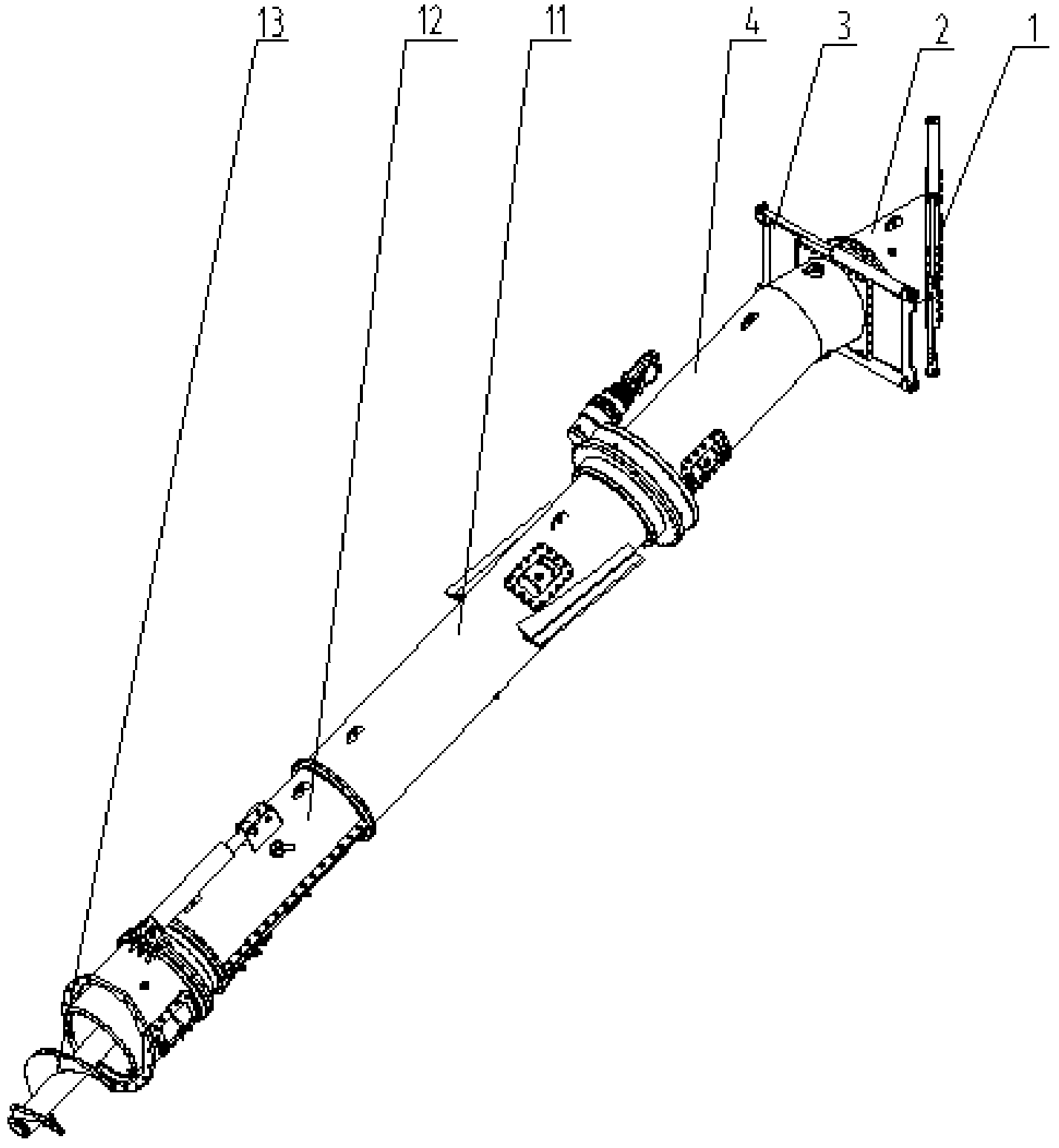
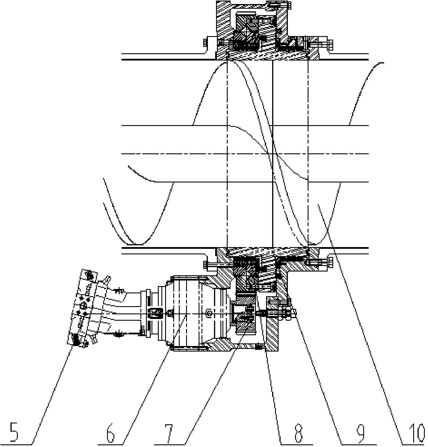
[0010] Referring to the accompanying drawings, the whole device consists of a secondary gate 1, a muck storage pipe 2, a primary gate 3, a conveying cylinder 4, a driving device 5, a reducer 6, a driving gear 7, a sealing device 8, a driven device 9, The driven blade 10, the second-stage conveying cylinder 11, the three-stage conveying cylinder 12, the screw conveying device 13 and the like are composed. The muck storage pipe 2 is installed between the secondary gate 1 and the primary gate 3, and a driving device 5, a reducer 6, a driving gear 7, and a sealing device 8 are installed between the first-stage conveying cylinder 4 and the second-stage conveying cylinder 11 , the driven device 9 , the driven blade 10 , and the screw conveying device 13 run through the one-stage conveying cylinder 4 , the second-stage conveying cylinder 11 and the three-stage conveying cylinder 12 .

[0011] A slag storage pipe 2 is installed between the secondary gate 1 and the primary gate 3 for s...


PUM


Abstract

The invention discloses a shaft-end deslagging spiral conveyer. The shaft-end deslagging spiral conveyer comprises conveying drums, a conveying threaded rod arranged in the conveying drums, and a driving mechanism for driving the conveying threaded rod. The shaft-end deslagging spiral conveyer is characterized in that the conveying drums at least include the first-section conveying drum and the second-section conveying drum, and the driving mechanism is arranged between the first-section conveying drum and the second-section conveying drum; the driving mechanism comprises an annular shell which is connected between the first-section conveying drum and the second-section conveying drum, and a driven ring is arranged and positioned in the annular shell through a bearing encircling the conveying threaded rod; the driven ring encircles the conveying threaded rod and is fixedly connected with the conveying threaded rod and is driven by a power unit. Through the shaft-end deslagging spiral conveyer, the deslagging function can be achieved without changing the flow direction of slag, intermediate driving is achieved, and the problem of eccentric wear of the threaded rod and the drums is effectively solved; a slag buffering and deslagging region is arranged, so blowout risks are effectively reduced, the tunnel construction progress and the safety performance are greatly improved, and the shaft-end deslagging spiral conveyer can be widely applied to the tunnel engineering construction machinery industry.

Description

Technical field: [0001] The invention relates to a screw slag discharge device of a tunnel engineering construction machine, in particular to a shield machine screw conveyor. Background technique: [0002] The slag discharge equipment is one of the important components of the shield tunneling machine used in tunnel construction. During the forward process of the shield machine, the slag in the soil bin needs to be discharged in time to accurately control the pressure of the muck in the soil bin. , resulting in precise control of surface uplift and subsidence. Although the existing technology can realize the screw slag discharge function, but because the shaft end drive is adopted, the drive system directly drives the screw rod. Obviously, the torque increases, and the screw rod is supported at one end, which is easy to be eccentrically worn with the cylinder, which changes the It is difficult to control the flow direction and the pressure of the soil bin, which is easy to c...

Claims


Application Information

Patent Timeline
IPC IPC(8): E21D9/12
Inventor 刘子铭刘双仲刘远征
Owner 辽宁三三工业有限公司
Why Eureka
Try Eureka