Air inlet humidifying system for ship diesel engine

A technology for marine diesel engines and humidification systems, applied in the direction of charging systems, mechanical equipment, engine components, etc. The low water utilization rate of the humidification system and other problems can achieve the effect of flexible and controllable water spray volume, good promotion and application value, and good water spray atomization effect

Inactive Publication Date: 2014-06-18
NO 711 RES INST CHINA SHIPPING HEAVY IND GRP
View PDF7 Cites 3 Cited by
  • Summary
  • Abstract
  • Description
  • Claims
  • Application Information

AI Technical Summary

Problems solved by technology

[0006] (1) Spray water directly at the intake port. For marine diesel engines, if water is sprayed directly at the intake port, due to the constraints of the size of the intake port, the number of nozzles allowed to be arranged is limited, and the atomized droplets are prone to collide with the wall. The condensation, the contact surface between intake air and atomized droplets is also small, and the efficiency of the entire intake humidification system is low
[0007] (2) The spraying method of water adopts the form of aerosol spraying, which has poor atomization quality and low water utilization rate, and it is necessary to control the water spray volume by controlling the pressure of the water circuit and the air circuit. complex
[0008] (3) The intake air is not heated, but the intake air is sprayed and humidified directly. The water utilization rate of the intake air humidification system is low; and the intake air temperature directly determines the maximum moisture absorption capacity of the intake air. The air is heated, it is difficult to meet the requirements of the moisture content of the intake air in engineering applications

Method used


Image

  • Air inlet humidifying system for ship diesel engine

Examples


Embodiment Construction

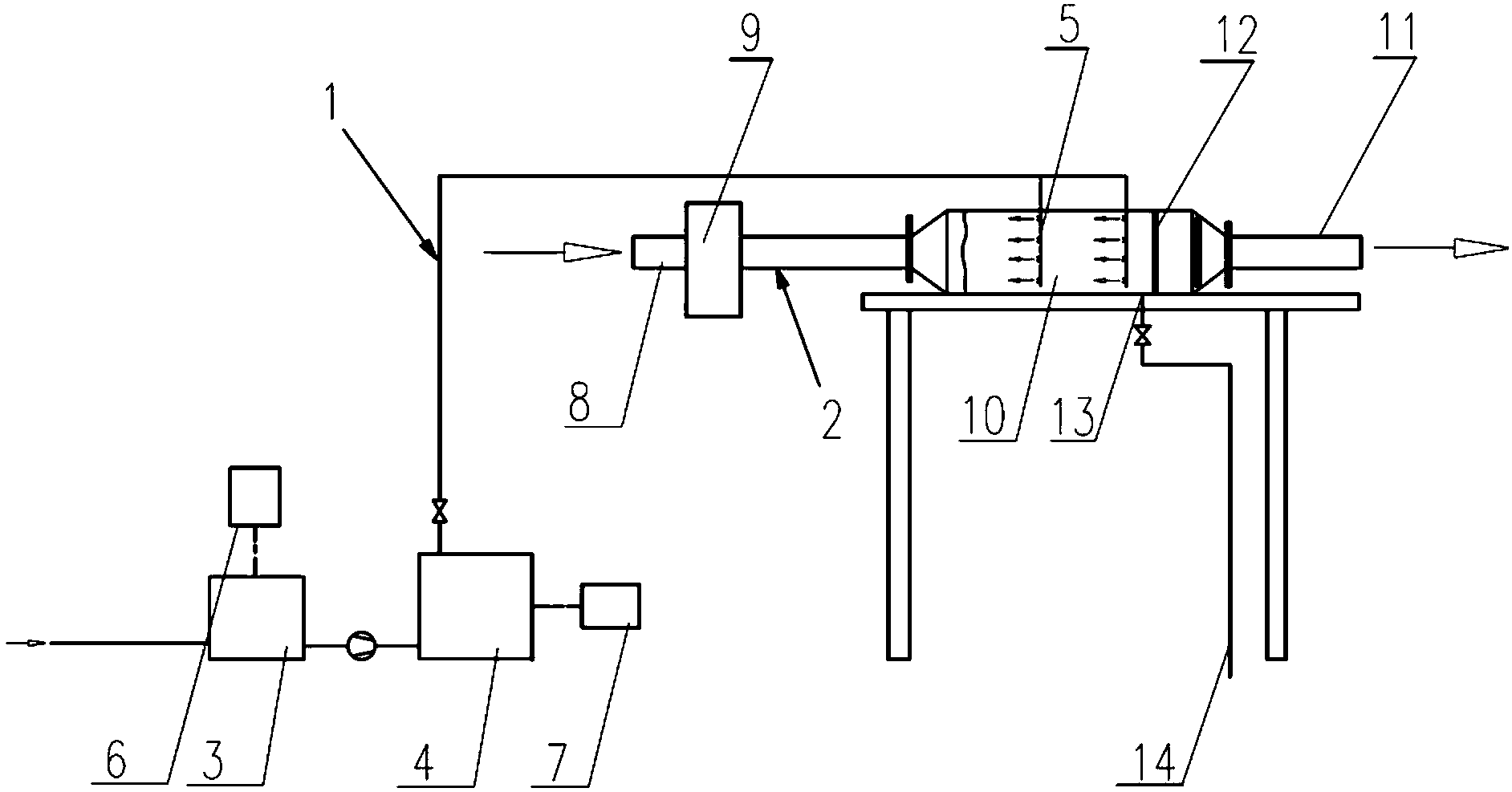
[0028] Such as figure 1 As shown, an air intake humidification system for a marine diesel engine includes a water injection pipeline 1 and an air intake pipeline 2 . Among them, the water spray pipeline 1 is provided with an automatic constant temperature water tank 3, a high-pressure micro-mist host 4 and a nozzle group 5 in sequence along the waterway direction. The automatic constant temperature water tank 3 is electrically connected with the auxiliary control box 6; the auxiliary control box 6 is used to control the liquid level and constant temperature of the water stored in the automatic constant temperature water tank 3. The high-pressure micro-mist host 4 is electrically connected to the main control box 7; the main control box 7 controls the opening and closing of each spray branch pipe in the nozzle group 5 through the high-pressure micro-mist host 4 (or solenoid valve).

[0029] The intake pipeline 2 is provided with an intake inlet 8, an intake heater 9, an intake...


PUM


Abstract

The invention discloses an air inlet humidifying system for a ship diesel engine. The air inlet humidifying system for the ship diesel engine comprises a water spraying pipeline and an air inlet pipeline. The water spraying pipeline is sequentially provided with an automatic constant temperature water tank, a high-pressure micro-mist main machine and a nozzle set in the water channel direction. The air inlet pipeline is sequentially provided with an air inlet heater and an air inlet humidifying tower in the air flow direction. The nozzle set extends into the air inlet humidifying tower. The water spraying direction of the nozzle set is opposite to the flowing direction of inflow air. A demister is arranged in the air inlet humidifying tower and located behind the nozzle set. A water discharging opening is formed in the air inlet humidifying tower. Liquid drops in the air inlet humidifying tower are discharged out of the air inlet humidifying tower by the water discharging opening through a water discharging pipeline. An outlet of the air inlet humidifying tower is connected with the air inlet pipeline of the diesel engine. The air inlet humidifying system for the ship diesel engine has the advantages of being good in water spraying effect and atomizing effect, large in maximum humidifying amount, flexible and controllable in water spraying amount, stable, reliable, high in efficiency, capable of satisfying the requirement for the moisture content of inflow air in engineering application and the like.

Description

technical field [0001] The invention relates to an intake air humidification system, in particular to an intake air humidification system of a marine diesel engine. Background technique [0002] During ship transportation, diesel engines will produce harmful gas and particulate matter emissions due to incomplete combustion of fuel, such as volatile organic compounds, chlorofluorocarbons, carbon monoxide, carbon dioxide, sulfur oxides, nitrogen oxides, smoke, etc. Among these pollutants, nitrogen oxides and sulfur oxides are the most harmful. Nitrogen oxides are mainly composed of NO and NO 2 Composition, they are commonly referred to as NO x . NO x The damage to the environment is great, not only endangering the human respiratory system, but also one of the main factors for the formation of photochemical smog near the ground. According to the data provided by Norway to the International Maritime Organization, the world's ships emit NO x up to 6.02 million tons, accounti...

Claims


Application Information

Patent Timeline
Patent Type & Authority Applications(China)
IPC IPC(8): F02M25/028F02M31/02
Inventor 刘瑞平涛张文正陈志忠
Owner NO 711 RES INST CHINA SHIPPING HEAVY IND GRP
Why Eureka
Try Eureka