spiral nozzle device

A technology of nozzle device and spiral nozzle, which is applied in the direction of spraying device, spraying device, etc., can solve the problems of high operation and maintenance cost, increased production and operation cost, and poor conditioning effect of evaporative cooler, so as to reduce equipment maintenance cost and improve Converter operating rate, the effect of improving production utilization

Active Publication Date: 2019-11-29
SHANDONG IRON & STEEL CO LTD
View PDF10 Cites 0 Cited by
  • Summary
  • Abstract
  • Description
  • Claims
  • Application Information

AI Technical Summary

Problems solved by technology

[0003] The imported dual-medium nozzle has the following problems in the production process: on the one hand, the structure is complex, and the helical channel is difficult to process; on the other hand, due to the small diameter of the helical channel, the channel is easily absorbed by impurities in the cooling water during the production process Blockage, resulting in short use time of dual-media nozzles and high frequency of blockage, resulting in the evaporative cooler being unable to control the temperature and affecting production; after the nozzle is blocked, it needs to be cleaned in time, resulting in high operation and maintenance costs; nozzle cleaning sometimes takes as long as six to eight hours, also affects production
In addition, the cost price of a single imported nozzle is 4,000 yuan, which is difficult to clean due to clogging, resulting in frequent replacement and increased production and operation costs; the workload of spot inspection personnel and equipment maintenance personnel is large, and it is easy to cause poor conditioning effect of the evaporative cooler. Affect the dust removal effect of the electrostatic precipitator

Method used


Image

  • spiral nozzle device
  • spiral nozzle device
  • spiral nozzle device

Examples


Embodiment Construction

[0034] The present invention will be described in detail below with reference to the accompanying drawings and examples. It should be noted that, in the case of no conflict, the embodiments in the present application and the features in the embodiments can be combined with each other.

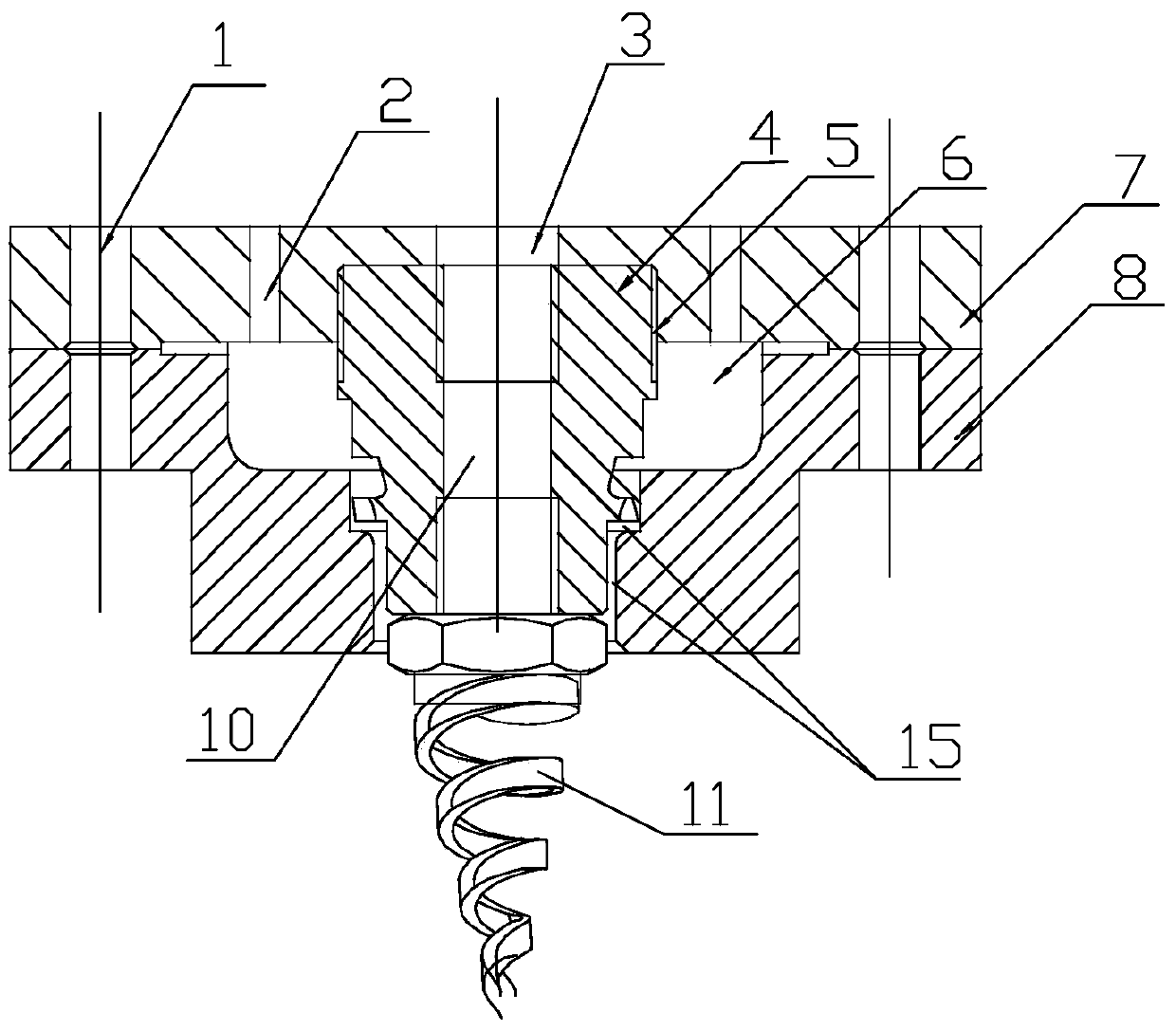
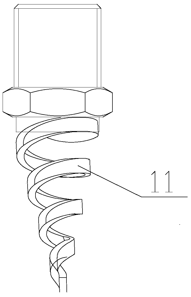
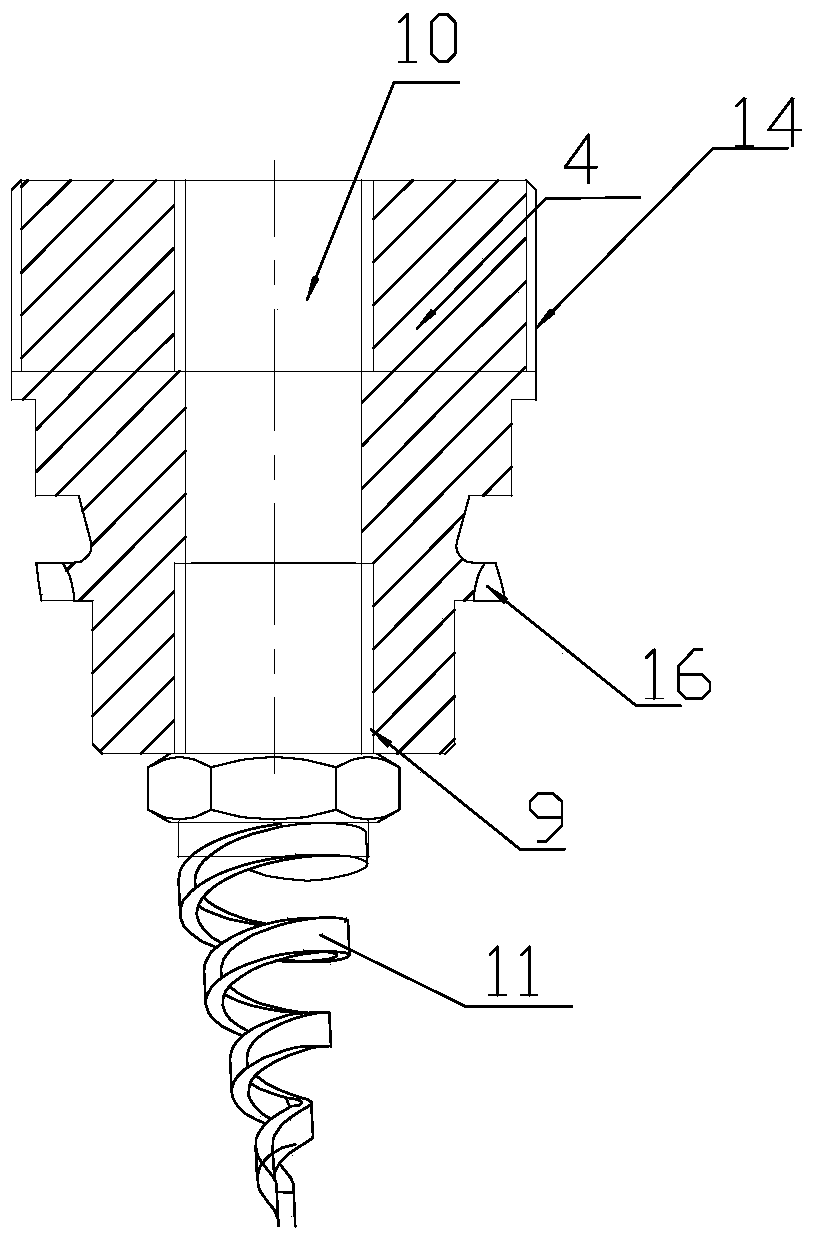
[0035] Such as Figure 1 to Figure 6 As shown, according to an embodiment of the present invention, a spiral nozzle device is provided, including: an outer flow atomization nozzle 8, a fixed flange 7, an inner flow atomization nozzle 4 and a spiral nozzle 11, wherein the fixed flange 7 The lower end is connected to the upper end of the outflow atomizing nozzle 8, the center part of the upper part of the fixed flange 7 is provided with a cooling water hole 3, the center part of the lower part of the fixed flange 7 is provided with a threaded hole 5, and the center part of the outflow atomizing nozzle 8 There is a through hole 15; the threaded hole 5 communicates with the through hole 15; the up...


PUM


Abstract

The invention provides a spiral nozzle device. The spiral nozzle device comprises an outer flow atomizing nozzle, a fixing flange, an inner flow atomizing nozzle and a spiral nozzle, wherein the lower end of the fixing flange is connected with the upper end of the outer flow atomizing nozzle, a cooling water hole is formed in the central part of the upper section of the fixing flange, a threaded hole is formed in the central part of the lower section of the fixing flange, and a through hole is formed in the central part of the outer flow atomizing nozzle; the threaded hole communicates with the through hole; the upper section of the inner flow atomizing nozzle is arranged in the threaded hole, the lower section of the inner flow atomizing nozzle is arranged in the through hole, a guide hole is formed in the central part of the inner flow atomizing nozzle, and the guide hole penetrates through the top end and the bottom end of the inner flow atomizing nozzle; the cooling water hole communicates with the guide hole; and the spiral nozzle is connected at the bottom end of the inner flow atomizing nozzle. The water atomizing effect of the spiral nozzle device provided by the invention is great.

Description

technical field [0001] The invention relates to iron and steel metallurgy mechanical equipment, in particular to a spiral nozzle device, which is applied to the cooling system of the evaporative cooler of the dry dust removal system for the flue gas of the iron and steel metallurgy intermediate converter. Background technique [0002] The dust removal evaporative cooler nozzle is one of the key components for the stable operation of the converter flue gas dry dust removal system. The equipment has been relying on imported nozzles to maintain production. The center of the fixed flange in the imported dual-medium nozzle is provided with a threaded through hole, and there are several steam channels around the threaded through hole. The steam channel is connected with an external steam source. The upper part of the internal flow atomizing nozzle is fixed on the threaded through hole of the fixed flange through threads. The upper surface of the internal flow atomizing nozzle is...

Claims


Application Information

Patent Timeline
Patent Type & Authority Patents(China)
IPC IPC(8): B05B1/34
CPCB05B1/3405
Inventor 周茂林曹桂菊张广鑫袁本明曹玉峰
Owner SHANDONG IRON & STEEL CO LTD
Why Eureka
Try Eureka