Rotary compressor

A technology of rotary compressors and compression devices, which is applied to rotary piston/swing piston pump components, mechanical equipment, machines/engines, etc., and can solve the problems of easy pressure fluctuations, burning of compressors, and oil accumulation on the upper part of compressor motors and other problems to achieve the effect of improving reliability, prolonging service life and ensuring oil storage

Inactive Publication Date: 2014-06-18
ANHUI MEIZHI PRECISION MFG
View PDF7 Cites 11 Cited by
  • Summary
  • Abstract
  • Description
  • Claims
  • Application Information

AI Technical Summary

Problems solved by technology

At such a high frequency, the pressure in the space above and below the motor drive part of the compressor tends to fluctuate, that is, if the pressure fluctuates greatly, it will easily cause oil accumulation on the upper part of the compressor motor
Once oil accumulates in the compressor, it will reduce the oil storage capacity in the lower oil pool of the compressor, which will affect the reliability of the moving parts of the compressor, and even cause the compressor to burn out
[0003] In addition, after the operating frequency of the compressor increases, the exhaust volume per unit time increases. Under the same compressor structure, the refrigerating machine oil in the exhaust airflow cannot be effectively separated, and will be discharged together with the exhaust airflow to the Excessive oil discharge occurs outside the compressor housing
When the oil output of the compressor is too large, it will also reduce the oil storage capacity of the oil pool in the lower part of the compressor, which will affect the reliability of the moving parts of the compressor, and even burn the compressor in severe cases.

Method used


Image

  • Rotary compressor
  • Rotary compressor
  • Rotary compressor

Examples


Embodiment Construction

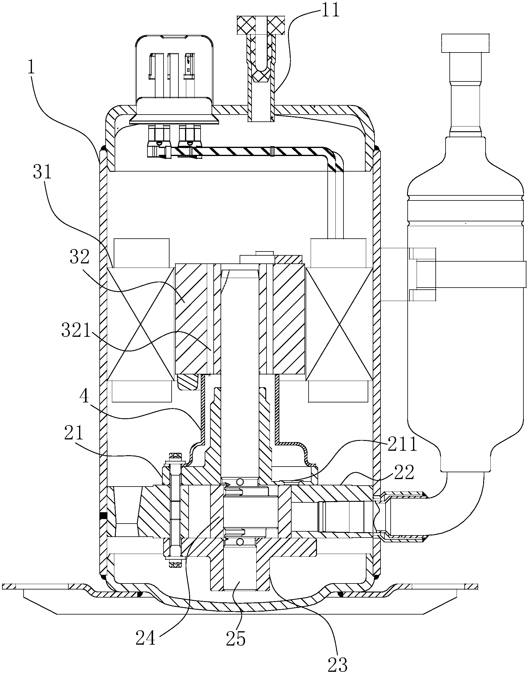
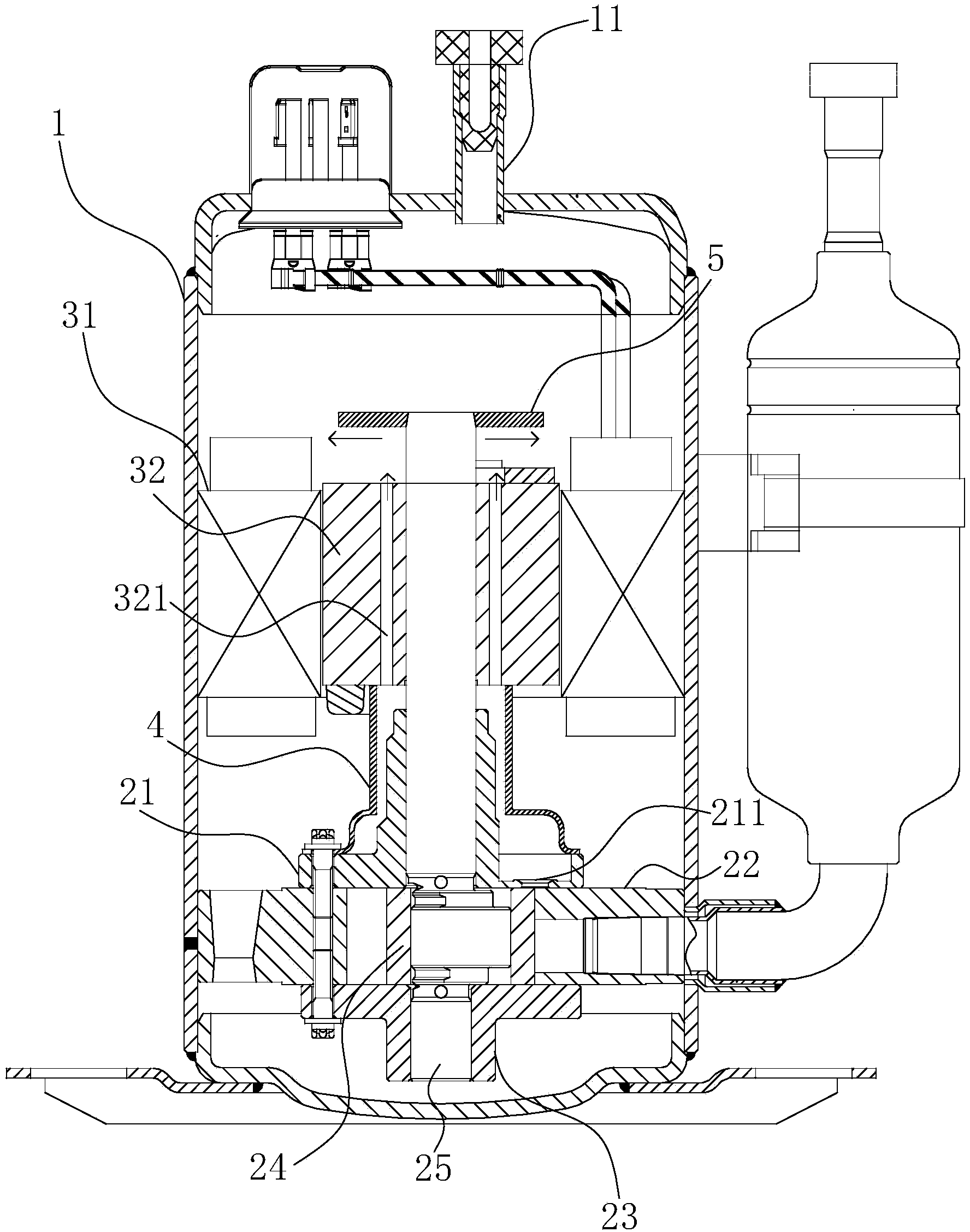
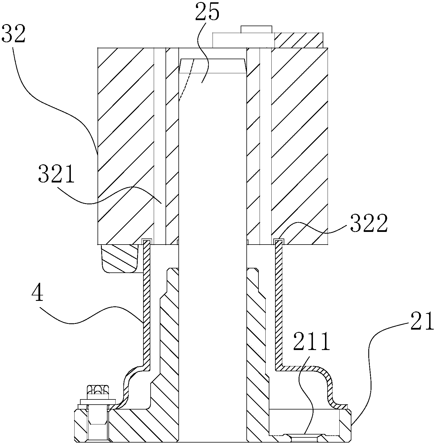
[0031] Embodiments of the present invention are described in detail below, examples of which are shown in the drawings, wherein the same or similar reference numerals designate the same or similar elements or elements having the same or similar functions throughout. The embodiments described below by referring to the figures are exemplary only for explaining the present invention and should not be construed as limiting the present invention.

[0032] In describing the present invention, it should be understood that the terms "center", "lateral", "width", "upper", "lower", "left", "right", "vertical", "horizontal", The orientation or positional relationship indicated by "top", "bottom", "inner", "outer", "clockwise", "counterclockwise", "axial", "radial", etc. are based on the orientation shown in the drawings Or positional relationship is only for the convenience of describing the present invention and simplifying the description, but does not indicate or imply that the device...


PUM


Abstract

The invention discloses a rotary compressor. The rotary compressor comprises a shell, a compression device, a motor and a gas guiding device, wherein the compression device is arranged in the shell, the motor is connected with the compression device to drive the compression device to compress refrigerants, the gas guiding device is arranged at one side, close to the motor, of the compression device, and at least part of the refrigerants outgoing from the compression device is introduced into the gas guiding device, and enters a space on one side, away from the compression device, of the motor in the shell, after passing through the gas guiding device and the motor. According to the rotary compressor, the pressure fluctuation at two sides of the motor is reduced due to the arrangement of the gas guiding device, and lubricating oil separated from the refrigerants can smoothly returns to an oil pool of the compressor, so that the lubricating oil flowing to the upper part of the motor along with the refrigerants is difficult to pile up at the upper end of the motor after being separated in the space on one side, away from the compression device, of the motor, and the oil reserve of the oil pool of the rotary compressor is ensured.

Description

technical field [0001] The invention relates to the field of refrigeration equipment, in particular to a rotary compressor. Background technique [0002] It is pointed out in related technologies that the frequency conversion compressor has a wide operating range. At present, the highest frequency of the compressor generally reaches 120 Hz, and even some manufacturers' products can reach 150 Hz. At such a high frequency, the pressure in the space above and below the motor drive part of the compressor tends to fluctuate, that is, if the pressure fluctuates greatly, it will easily cause oil accumulation on the upper part of the compressor motor. Once oil accumulates in the compressor, it will reduce the oil storage capacity in the lower oil pool of the compressor, which will affect the reliability of the moving parts of the compressor, and even cause the compressor to burn out. [0003] In addition, after the operating frequency of the compressor increases, the exhaust volume...

Claims


Application Information

Patent Timeline
Patent Type & Authority Applications(China)
IPC IPC(8): F04C29/02F04C29/06
Inventor 吴延平谢婉
Owner ANHUI MEIZHI PRECISION MFG
Why Eureka
Try Eureka