Electromagnetic clutch
An electromagnetic clutch and excitation coil technology, applied in the field of clutches, can solve the problems of unsynchronized tightening or unscrewing deformation, unbalanced friction force, etc.
- Summary
- Abstract
- Description
- Claims
- Application Information
AI Technical Summary
Problems solved by technology
Method used
Image

Examples
Embodiment 1
[0029] The electromagnetic clutch of the compressor is set on the path where the engine transmits the rotational force to the compressor, so that the power transmission can be continued or stopped. The compressor includes a main shaft 30 driven to rotate and a compression mechanism (not shown). When the electromagnetic clutch is engaged, the rotational force on the engine is transmitted to the main shaft 30 through the electromagnetic clutch. When the main shaft 30 rotates, the compression mechanism gives a load to the main shaft 30. When the load is too large, the attraction force on the electromagnetic clutch may be insufficient to cause slippage.
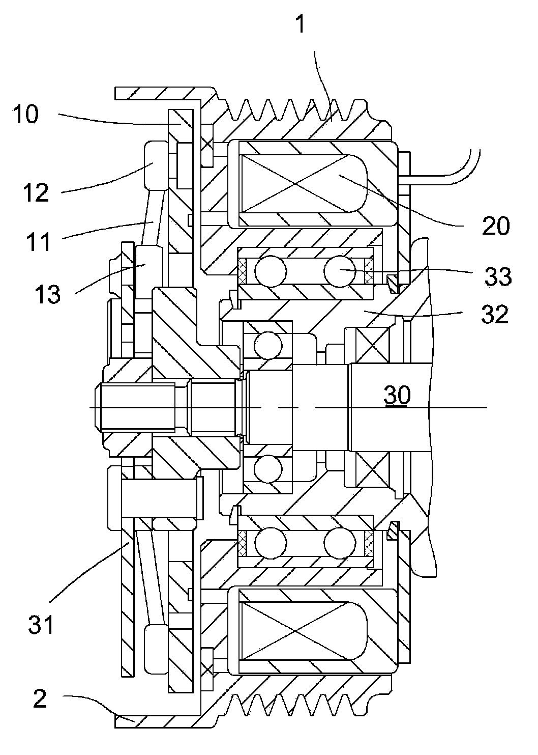
[0030] like figure 2 As shown, the electromagnetic clutch includes a pulley 1, and the engine drives the pulley 1 through a belt; a hub 31; a suction cup 10 opposite to the pulley 1; and a coil 20 arranged in the ring groove of the pulley 1. Wherein, the hub 31 is sleeved on the outer periphery of the compressor main shaft 30,...
Embodiment 2
[0035] In order to improve the frictional force between the flange 2 of the pulley 1 and the elastic body 11, as Figure 7 As shown, the groove 4 is processed on the inner periphery of the flange 2, and the number of the groove 4 is an integer multiple of the elastic body 11. When the elastic member 11 moves to the position of the groove 4 in the third stage, the elastic member 11 and the groove 4 More pronounced deformation occurs in the contact parts, thus increasing friction.
Embodiment 3
[0037] The difference from Example 1 is that, as Figure 8 As shown, in a natural state, the elastic body 11 is in an inwardly concave arc shape, and correspondingly, the inner edge of the pulley 1 protrudes axially from the flange 5 toward the suction cup 10 (will pass through the central hole of the suction cup 10 ). In the same way, the above-mentioned actions in the first to fifth stages are generated.
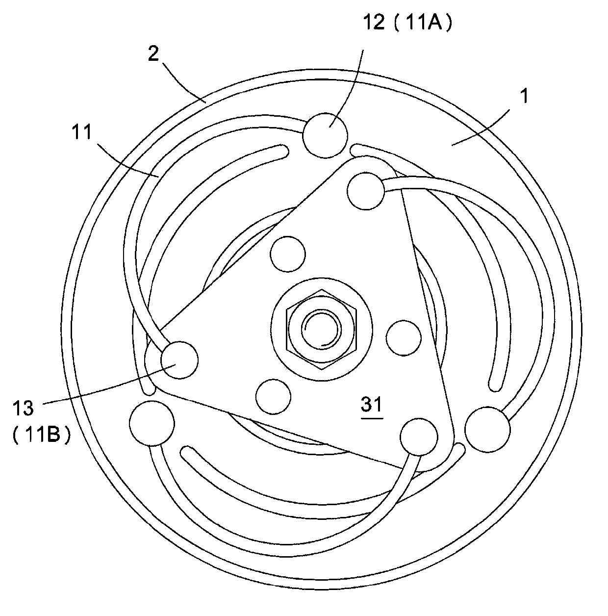
[0038]In a natural state, the elastic body 11 is separated from the flange 5 . In the first stage of the clutch operation, the coil 20 is energized, the pulley 1 attracts the suction cup 10, causing the elastic body 11 to elongate in the axial direction, the suction cup 10 and the pulley 1 are attracted, the suction cup 10 is driven by the pulley 1, and rotates in the R direction, and the end 11B Located in front of the rotation of the end portion 11A, the spindle 30 has not yet started to rotate due to the load at the moment when the suction cup 10 is activated. In the ...
PUM
 Abstract
Description
Claims
Application Information
 - R&D
- Intellectual Property
- Life Sciences
- Materials
- Tech Scout
- Unparalleled Data Quality
- Higher Quality Content
- 60% Fewer Hallucinations
Browse by: Latest US Patents, China's latest patents, Technical Efficacy Thesaurus, Application Domain, Technology Topic, Popular Technical Reports.
© 2025 PatSnap. All rights reserved.Legal|Privacy policy|Modern Slavery Act Transparency Statement|Sitemap|About US| Contact US: help@patsnap.com