Electric control valve

An electric control valve and valve body technology, which is applied to the valve details, valve device, valve shell structure, etc., can solve the problems that the welding parts are easy to be corroded

Active Publication Date: 2014-06-18
ZHEJIANG SANHUA INTELLIGENT CONTROLS CO LTD
View PDF7 Cites 2 Cited by
  • Summary
  • Abstract
  • Description
  • Claims
  • Application Information

AI Technical Summary

Problems solved by technology

[0008] In view of the above defects, the technical problem to be solved by the present invention is to provide an electric control valve to solve the

Method used


Image

  • Electric control valve
  • Electric control valve
  • Electric control valve

Examples


no. 1 approach

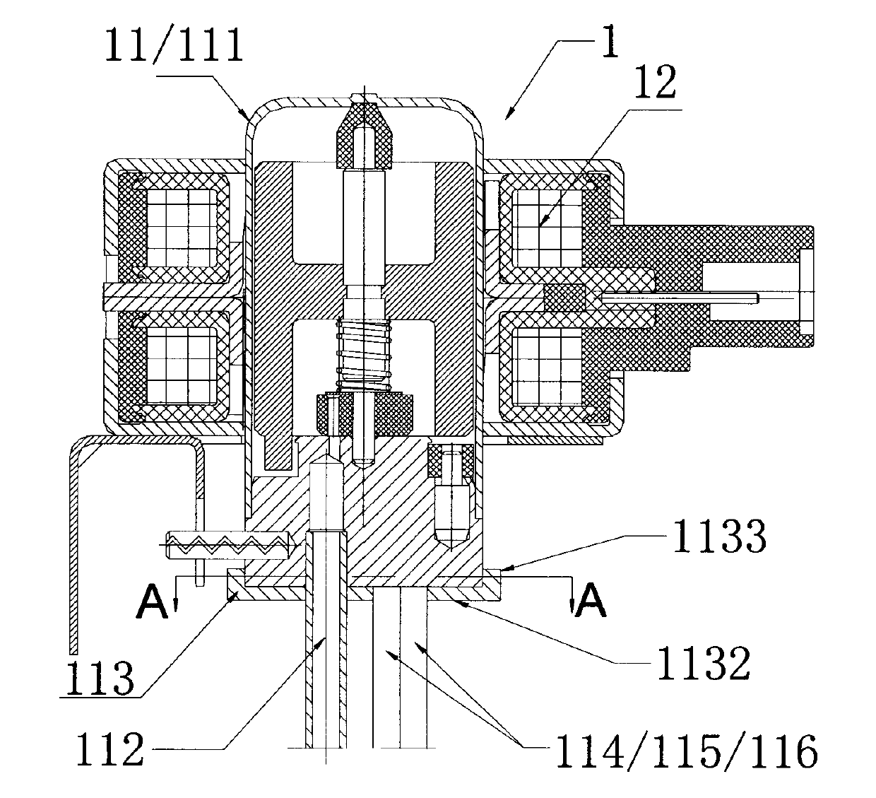
[0027] Please refer to figure 1 , figure 2 , figure 1 is a schematic diagram of the electric control valve according to the first embodiment of the present invention, figure 2 Yes figure 1 A-A cross-sectional view. The electric control valve 1 includes a valve body part 11 and a coil part 12, and the valve body part 11 is composed of a valve body 111 and a connecting pipe. In this embodiment, the electric control valve 1 is used to switch the refrigerant flow path, and has one inlet and three outlets, wherein the inlet is welded and fixed with an inlet connecting pipe 112, and the three outlets are respectively welded with outlet connecting pipes 114 / 115 / 116.

[0028] The relative positions of the valve body part 11 and the coil part 12 can be fixed by a fixing method generally adopted in the prior art, which is not limited in this embodiment.

[0029] In this embodiment, the electric control valve 1 also includes a protection device. Specifically, the protection devi...

no. 2 approach

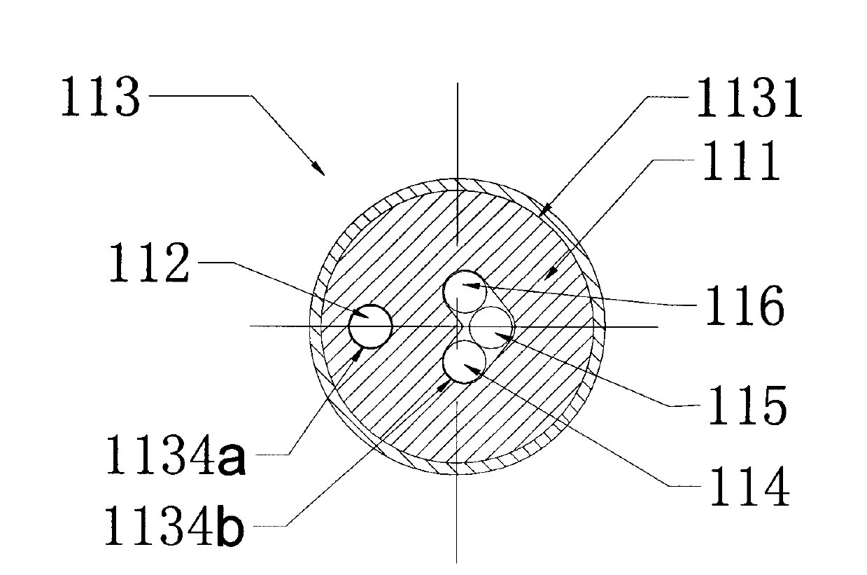
[0036] Attached below image 3 , to describe the second embodiment of the present invention.

[0037] The second embodiment is an improvement made on the first embodiment. The electric control valve with three outlets is still used as an example for illustration. Based on the enlightenment of the present invention, those skilled in the art can also apply this embodiment to different outlets. Among the number of electric control valves. In addition, the same parts as those in the above-mentioned first embodiment will not be repeated, and only the differences will be described.

[0038] Please refer to image 3 . image 3 It is a schematic diagram of the electric control valve according to the second embodiment of the present invention.

[0039] The protective cover 113 is generally in a cylindrical shape, surrounded by a peripheral wall 1133 to form an accommodating cavity 1131 , and has a bottom 1132 . A channel portion 1134 is opened on the bottom plane, and the shape of...

no. 3 approach

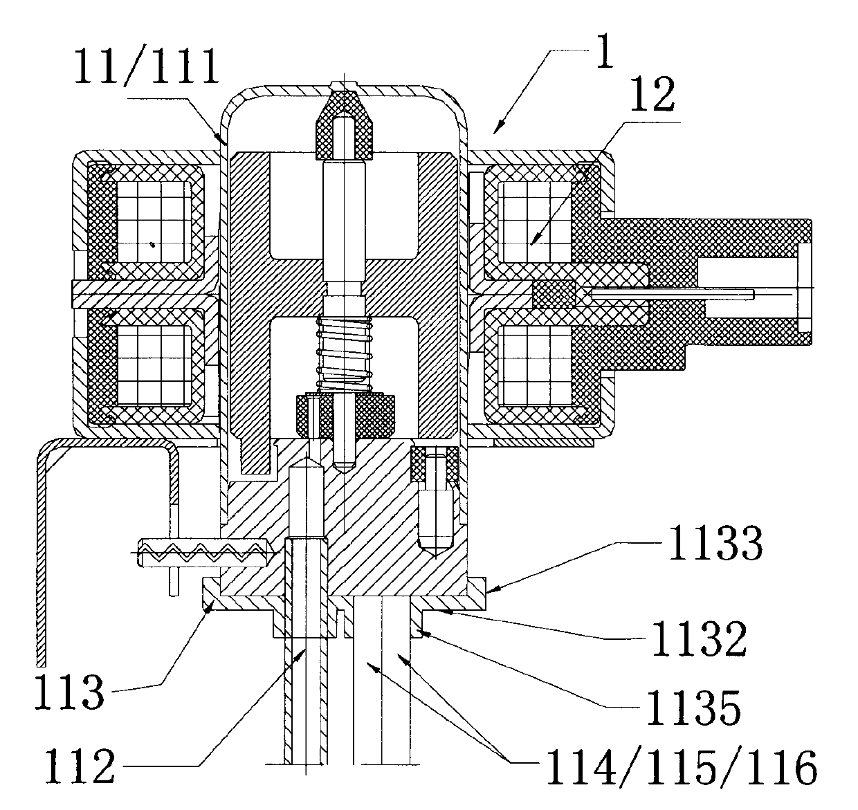
[0045] Combine below Figure 4 , Figure 5 , the third embodiment of the present invention will be described.

[0046] The third embodiment is a further optimization of the second embodiment. like Figure 4 , Figure 5 as shown, Figure 4 It is a schematic diagram of the electric control valve according to the third embodiment of the present invention, Figure 5 It is a structural schematic diagram of the protective cover of the third embodiment.

[0047] Of course, the same optimization can also be performed on the basis of the first embodiment to obtain a new technical solution.

[0048] The difference from the second embodiment is that the protective sleeve 113 is also provided with a first connecting portion, the first connecting portion is arranged on the other end surface opposite to the bottom surface 1132 of the protective sleeve 113 and protrudes from the end of the protective sleeve 113 in the radial direction. side edge. The first connecting part is specific...


PUM


Abstract

The invention discloses an electric control valve. The electric control valve comprises a valve body component and a coil component, wherein the valve body component comprises a valve body and a connecting pipe which is fixedly welded to the valve body and communicates the interior and exterior of the valve body. The electric control valve is characterized by also comprising a protecting device, wherein the protecting device encloses the combining part between the valve body and the connecting pipe. The combining part between the valve body and the connecting pipe is enclosed by the connecting pipe, so that the welding part between the valve body and the connecting pipe can be well protected. A first connecting part and a mounting part can also be additionally arranged on a protecting sleeve, so that a protecting function, a fixing function and a mounting function are also realized, fixing devices and mounting components for the valve body and a coil in the prior art can also be saved, and meanwhile, the manufacturing cost can also be greatly reduced.

Description

technical field [0001] The invention relates to the technical field of refrigeration, in particular to an electric control valve used in a refrigeration system for switching channels or regulating flow. Background technique [0002] With the development of science and technology, the progress of society and the continuous improvement of people's living standards, the application of household appliances such as air conditioners and refrigerators is almost everywhere in production and life. [0003] At present, electric control valves are widely used in air conditioners, refrigerators and other refrigeration systems. The electric control valve is generally composed of two parts, the valve body part and the coil part. It mainly uses the electromagnetic force generated by the electromagnetic coil to drive the valve core or other moving parts of the valve body part to move, so as to realize the control of the opening of the valve port or the flow channel. switching etc. [0004...

Claims


Application Information

Patent Timeline
IPC IPC(8): F16K27/08F16K31/04
CPCF16K27/12F16K31/06
Inventor 不公告发明人
Owner ZHEJIANG SANHUA INTELLIGENT CONTROLS CO LTD
Why Eureka
Try Eureka