LED bulb

A technology for LED bulbs and radiators, which is applied in lampshades, cooling/heating devices of lighting devices, lighting and heating equipment, etc., can solve the problems of short creepage distance, unreachable, and high cost.

Inactive Publication Date: 2014-06-18
OPPLE LIGHTING
View PDF7 Cites 0 Cited by
  • Summary
  • Abstract
  • Description
  • Claims
  • Application Information

AI Technical Summary

Problems solved by technology

However, its alumina ceramic substrate is close to the heat sink and is in thermal contact with the heat sink, so that the creepage distance between the alumina layer and the heat sink is too short to meet the required standard
If sufficient creepage distance is required, the thickness of the ceramic substrate needs to be increased, resulting in increased cost and increased weight of the bulb lamp

Method used


Image

  • LED bulb
  • LED bulb
  • LED bulb

Examples


Embodiment Construction

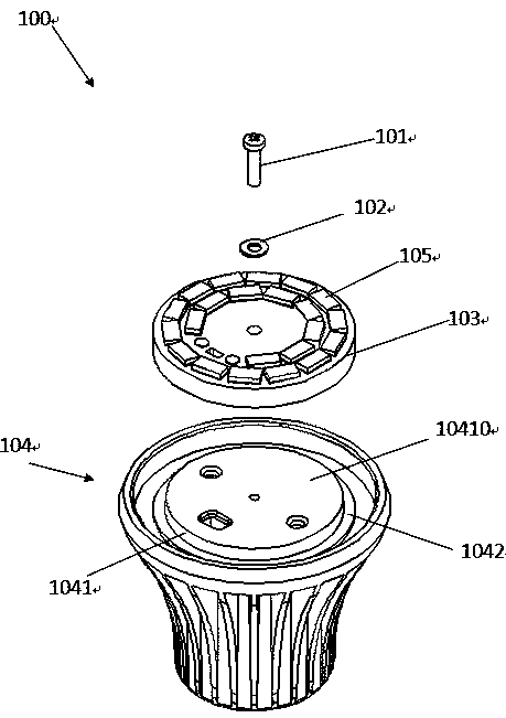
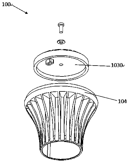
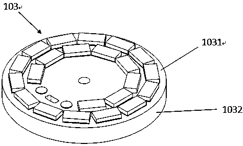
[0011] refer to Figure 1 to Figure 3 As shown, the figure shows the first preferred embodiment of the present invention. In this embodiment, the LED bulb 100 includes a heat sink 104 , a ceramic substrate 103 in contact with the heat sink 104 , and an LED light source 105 mounted on the ceramic substrate 103 .

[0012] The heat sink 104 has a protrusion 1041 , and the protrusion 1041 is connected with the ceramic substrate 103 to form a first connection surface 10410 . The ceramic substrate 103 has a second connection surface 1030 connected to the protrusion 1041 , and the area of ​​the first connection surface 10410 of the protrusion 1041 is smaller than the area of ​​the second connection surface 1030 of the ceramic substrate 103 . The radiator 104 further includes a main body 1042 connected to the boss 1041 , the main body 1042 of the radiator 104 and the boss 1041 form a stepped internal structure of the radiator 104 .

[0013] The ceramic substrate 103 includes a flat p...


PUM


Abstract

The invention provides an LED (Light Emitting Diode) bulb. The LED bulb comprises a radiator, a ceramic substrate in contact with the radiator, and an LED light source fixed on the ceramic substrate, wherein the radiator is provided with a boss, the boss is provided with a first connection surface formed in connection with the ceramic substrate, the ceramic substate is provided with a second connection surface formed in connection with the boss, and the area of the first connection surface is smaller than that of the second connection surface.

Description

【Technical field】 [0001] The invention relates to an illuminating device, in particular to an LED illuminating device. 【Background technique】 [0002] With the development of LED technology, more and more LED light bulbs are applied to lighting devices such as lamps. Traditional LED light bulbs use aluminum substrates as substrates to install LED light sources. With the advancement of technology, ceramic substrates are increasingly used as substrates for LED light sources due to their excellent thermal conductivity and reliable electrical insulation. In the prior art, Chinese Patent Application Publication No. CN10277776A discloses an alumina ceramic LED light bulb. The alumina ceramic LED light bulb includes an alumina ceramic substrate, a radiator and a lampshade. Some radiators are made of metal, so the shortest distance between two conductor parts (the edge of the conductive part on the surface of the ceramic substrate to the part where the radiator is connected to the...

Claims


Application Information

Patent Timeline
Patent Type & Authority Applications(China)
IPC IPC(8): F21S2/00F21V17/10F21Y101/02
CPCF21S8/04F21Y2101/02F21V3/00F21V29/2231F21K9/135F21S8/02F21Y2103/022F21K9/232F21V3/02F21V29/773F21Y2103/33F21Y2115/10
Inventor 王耀海
Owner OPPLE LIGHTING
Why Eureka
Try Eureka