Routing switching method and device for ring optical transmission network

A technology of transmission network and ring light, which is applied in the field of optical transmission network, can solve the problems of long time-consuming, inoperable optical routing, low efficiency, etc., and achieve the effect of fast processing and no impact on network operation

Active Publication Date: 2017-05-03
CHINA MOBILE GROUP SHANDONG
View PDF5 Cites 0 Cited by
  • Summary
  • Abstract
  • Description
  • Claims
  • Application Information

AI Technical Summary

Problems solved by technology

[0007] Embodiments of the present invention provide a route switching method and device for a ring optical transmission network, which is used to solve the situation in the prior art that the optical route of one base station cannot work and another base station is powered off in the ring optical transmission network in the prior art. The problem that led to the decommissioning of the entire optical ring network, the solution is inefficient, time-consuming, and significantly affects the operation of the ring optical transmission network

Method used


Image

  • Routing switching method and device for ring optical transmission network
  • Routing switching method and device for ring optical transmission network
  • Routing switching method and device for ring optical transmission network

Examples


Embodiment 1

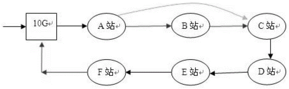
[0025] The embodiment of the present invention first proposes a route switching method to perform route switching when the base station in the ring optical transmission network is powered off.

[0026] figure 2 shows the workflow of the route switching method applied to the ring optical transmission network provided by the embodiment of the present invention, the method includes:

[0027] Step 201, monitoring whether the main optical route and the backup optical route connected to the base station and its two adjacent base stations are working normally; and monitoring whether the output voltage of the base station power supply in the base station is less than a predetermined voltage threshold;

[0028] Specifically, the operation of monitoring whether the optical routing works normally is: monitoring whether the power of the optical signal sent and received by the base station is normal;

[0029] Specifically, the predetermined voltage threshold is greater than or equal to t...

Embodiment 2

[0074] The embodiment of the present invention also provides a processing solution for a base station to passively switch routes according to an instruction from a remote terminal.

[0075] Image 6 It shows the working process of the route switching method applied to the ring optical transmission network provided by the embodiment of the present invention, as shown in Image 6 As shown, the method includes:

[0076] Step 601, receiving a first switching instruction or a second switching instruction from a remote terminal, where the first switching instruction or the second switching instruction includes authority information;

[0077] Step 602, authenticating the authority information in the first switching instruction or the second switching instruction;

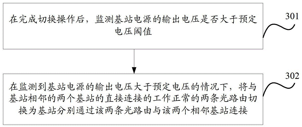
[0078] Step 603: In the case that the authority information in the first switching instruction passes the authentication, switch the two normal optical routes connected to the base station and its two neighboring base st...


PUM


Abstract

The invention discloses a route switching method and device for a ring-shaped optical transmission network. The method includes: when the output voltage of the power supply of the monitored base station is lower than a predetermined voltage threshold, according to the monitored optical route that works normally, the base station is connected to the The two normally working optical routes connected to two adjacent base stations are switched to the direct connection of the two optical routes, so that once it is detected that the base station is about to be powered off, the base station can be withdrawn from the ring optical transmission network, and the base station will be connected with the base station The two adjacent base stations are directly connected, the processing process can be automatically executed, the processing process is fast and effective, and has almost no impact on the network operation, thereby avoiding the simultaneous existence of a base station in the ring optical transmission network in the prior art that cannot work, and Another power outage at the base station will lead to the decommissioning of the entire optical ring network. The solution is inefficient, time-consuming, and significantly affects the operation of the ring optical transmission network.

Description

technical field [0001] The invention relates to an optical transmission network, in particular to a routing switching method and device for a ring optical transmission network. Background technique [0002] At present, the structure of the optical transmission network is usually a ring network (commonly called an optical ring network), and each node in the ring network can be a base station or other network equipment, and the function of network switching can be realized conveniently through the ring network structure. For example, if a base station fails in the ring network, the original transmission direction will be switched in the reverse direction of the original transmission direction, so as to ensure service continuity. [0003] However, in the optical ring network, if a base station fails to work due to equipment failure or optical routing failure, and another base station loses power when the failure is not repaired, at the moment when the base station loses power a...

Claims


Application Information

Patent Timeline
Patent Type & Authority Patents(China)
IPC IPC(8): H04B10/03H04B10/07H04W24/04
Inventor 公法军顾辰龙周大祥王春蕾
Owner CHINA MOBILE GROUP SHANDONG
Why Eureka
Try Eureka