Solar cellphone charging jacket

A mobile phone charging and solar panel technology, applied in collectors, electric vehicles, electrical components, etc., can solve the problems of prolonging the standby and use time of mobile phones, the single function of the sheath, and the limited standby and use time of mobile phones, etc., to achieve beautiful appearance Generous, high charging efficiency, guaranteed long-term standby and use effect

Inactive Publication Date: 2014-06-25
SHENZHEN SACRED IND
View PDF11 Cites 6 Cited by
  • Summary
  • Abstract
  • Description
  • Claims
  • Application Information

AI Technical Summary

Problems solved by technology

This kind of sheath has a relatively single function and cannot meet people's long-term entertainment needs. Therefore, people begin to install rechargeable batteries on the sheath body, thereby prolonging the standby and use time of mobile phones.
However, even with a rechargeable battery, the standby and use time of the mobile phone is still quite limited, which is still unsatisfactory for users who go on business or travel outdoors for a long time.

Method used


Image

  • Solar cellphone charging jacket
  • Solar cellphone charging jacket
  • Solar cellphone charging jacket

Examples


Embodiment approach 1

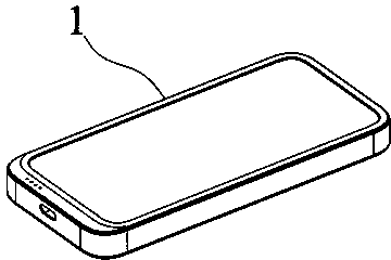
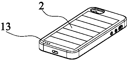
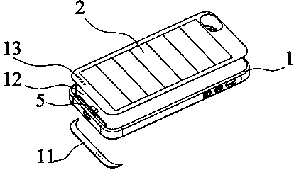
[0035] Such as Figures 1 to 6 And shown in 10, a kind of solar mobile phone charging sheath, comprises sheath body 1, solar panel 2, integrated circuit 3 and charging output port 5, sheath body 1 front is provided with a cavity corresponding to the position of mobile phone charging port, The integrated circuit 3 is installed in the cavity, a decorative cover 11 is arranged above it, and a slot 12 is arranged on the back panel of the sheath body 1 . The solar panel 2 is a high-efficiency solar panel, mainly composed of a PCB substrate 21 , a high-efficiency solar module 22 and a transparent protective layer 23 . The substrate 21 can be bent in an arc and used for back connection to carry the solar module 22; the solar module 22 is connected in series by a number of high-efficiency solar cells that can be bent along an arc to form a plate-shaped solar module 22, and the solar module 22 is fixed on the PCB On the substrate 21; a transparent protective layer 23 fixedly covering ...

Embodiment approach 2

[0038] Such as Figures 7 to 9 As shown in and 10, a charging sheath for a solar mobile phone includes a sheath body 1, a solar panel 2, an integrated circuit 3, a rechargeable battery 4 and a charging output port 5. There is a cavity, the integrated circuit 3 is installed in the cavity, a decorative cover 11 is arranged above it, and a slot 12 is arranged on the back panel of the sheath body 1 . The solar cell panel 2 is a bendable monocrystalline silicon high-efficiency solar cell panel, which is mainly composed of a PCB substrate 21 , a solar module 22 and a transparent protective layer 23 . The substrate 21 can be curved in an arc to carry the solar module 22; the solar module 22 is composed of a number of high-efficiency solar cells that can be bent along an arc in series to form a plate-shaped solar module 22, and the solar module 22 is fixed on the substrate 21; transparent The protective layer 23 is fixedly covered on the surface of the solar module 22 for protecting ...


PUM


Abstract

The invention discloses an efficient solar cellphone charging jacket comprising a jacket body (1), a solar cell panel (2), an integrated circuit (3) and a cellphone charging port (5), wherein the solar cell panel (2) is embedded on the jacket body (1) for converting solar energy into electric energy, and the integrated circuit is used for regulating voltage and stabilizing current to charge a cellphone sleeved by the jacket body (1). The efficient solar cellphone charging jacket disclosed by the invention has high charging efficiency, thereby capable of fully charging the cellphone within a short period; and back electrode connection technology is adopted, so that the outline is attractive and elegant. Furthermore, an efficient bent solar cell is combined on the cellphone jacket to both protect the cellphone shell from being scratched and provide continuous power supply to the cellphone through the efficient solar cell panel so as to guarantee long time standby and use of the cellphone.

Description

technical field [0001] The invention relates to a mobile phone charging sheath, in particular to a solar computer charging sheath which can use solar energy to charge a mobile phone. Background technique [0002] At present, mobile phones, especially smart phones, are deeply loved by people for their intelligence and entertainment, and have become the new darling of mobile communications. In order to protect the exquisite shell of the smartphone, the sheath matching the mobile phone came into being. The mobile phone sheath in the prior art includes a sheath body, and the sheath body can be attached to the shell of the mobile phone to protect the shell of the mobile phone from being scratched by hard objects. This sheath has a relatively single function and cannot meet people's long-time entertainment needs. Therefore, people begin to install rechargeable batteries on the sheath body, thereby prolonging the standby and use time of the mobile phone. However, even with a rech...

Claims


Application Information

Patent Timeline
Patent Type & Authority Applications(China)
IPC IPC(8): A45C11/24H02J7/00
Inventor 韦海贵
Owner SHENZHEN SACRED IND
Why Eureka
Try Eureka