Display cabinet
A display cabinet and showroom technology, applied in the field of display cabinets, can solve the problems of high cost and complicated structure
- Summary
- Abstract
- Description
- Claims
- Application Information
AI Technical Summary
Problems solved by technology
Method used
Image

Examples
Embodiment 1)
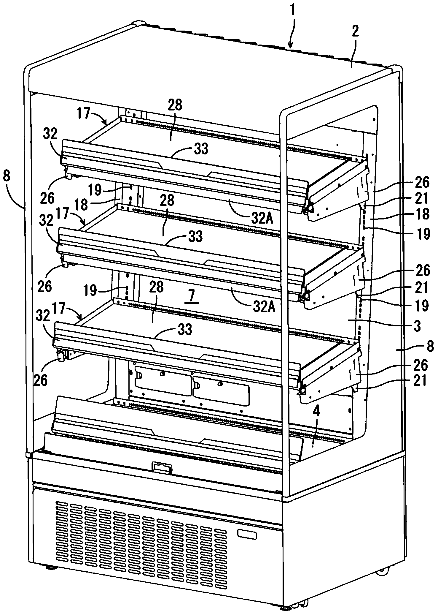
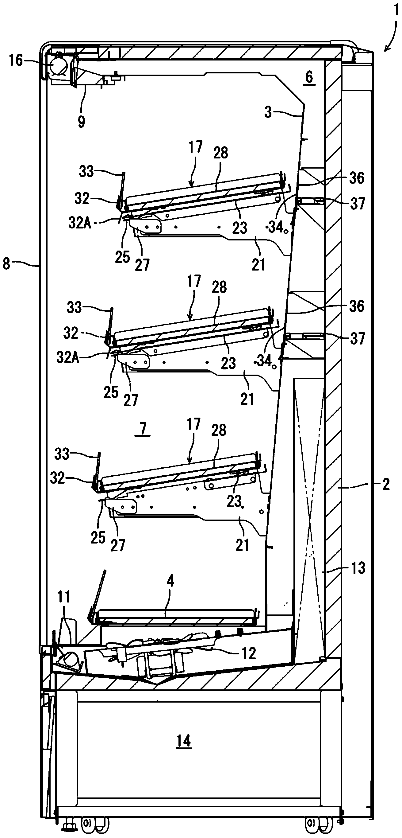
[0073] The showcase 1 of the embodiment is used for displaying and selling products such as canned beverages or plastic bottled beverages in stores such as supermarkets or convenience stores. A partition plate 3 is arranged at intervals inside the heat insulating wall 2 , and a table top 4 is provided at a space between the lower end of the partition plate 3 and the bottom wall of the heat insulating wall 2 . Moreover, a series of cold air passages 6 are formed between these partition plates 3 , the table top 4 and the heat insulating wall 2 , and a showroom 7 with a front opening is formed inside the partition board 3 and the table top 4 . In addition, 8 and 8 are side panels on which transparent glass is installed, and are installed on both sides of the heat insulating wall 2 .
[0074] A cold air discharge port 9 is formed on the upper edge of the front opening of the showroom 7, and a cold air intake port 11 is formed on the lower edge, and these ports communicate with the...
Embodiment 2)
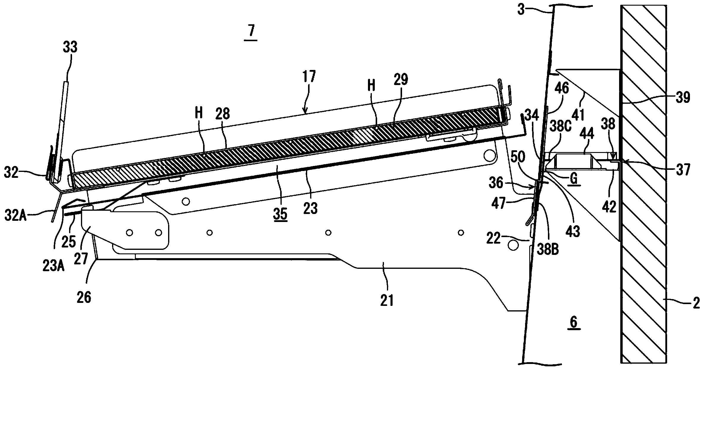
[0105] then, Figure 20 , Figure 21 , Figure 22 Indicates other examples. In addition, in each figure, by and Figure 1 to Figure 19 Components represented by the same symbols are the same or play the same role. In this case, the front edge 38B of the baffle holder 37 rises at a predetermined interval on the cold air duct 6 side of the partition plate 3 as a whole, and reaches the front ends of the left and right sides 38C, 38D. A rectifying portion 49 composed of a through hole 48.
[0106] Further, the straightening portion 49 corresponds to the discharge port 34 , and the left and right clamping portions 43 are configured at both ends of the straightening portion 49 located outside the both side edges of the discharge port 34 . By forming such a rectifying portion 49 on the baffle holder 37, the cold air discharged from the discharge port 34 can be rectified, or the height or discharge amount of the discharge portion can be adjusted, so that an appropriate amount can...
Embodiment 3)
[0108] then, Figure 23 , Figure 24 , Figure 25 Still another example is shown. In addition, in each figure, by and Figure 1 to Figure 19 Components represented by the same symbols are the same or play the same role. In this case, a plurality of protrusions 51 extending through the front and rear are formed on the brace 23 . Moreover, each protrusion 51 is arrange|positioned so that a front part may spread in the left-right direction.
[0109] The cool air discharged from the discharge port 34 of the partition plate 3 and guided by the operation portion 47 of the baffle plate 36 to reach the bottom of the suction port 23 is rectified by the protruding strip 51 and diffused in the left and right directions to reach the front of the shelf 17 . As a result, the cold air can be evenly discharged downward from the shelf 17, and the cooling of the left and right corners in the showroom 7 where the cold air is relatively insufficient can also be compensated.
[0110] In addi...
PUM
 Abstract
Description
Claims
Application Information
 - R&D Engineer
- R&D Manager
- IP Professional
- Industry Leading Data Capabilities
- Powerful AI technology
- Patent DNA Extraction
Browse by: Latest US Patents, China's latest patents, Technical Efficacy Thesaurus, Application Domain, Technology Topic.
© 2024 PatSnap. All rights reserved.Legal|Privacy policy|Modern Slavery Act Transparency Statement|Sitemap