Pre-forming die of automobile engine exhaust system manifold

A technology for exhaust system manifolds and automobile engines, which is applied in the field of stamping processing of parts and components, can solve problems such as insufficient compaction of workpieces, and achieve the effect of ensuring compaction

Active Publication Date: 2014-06-25
WUXI DAWN DIE & STAMPING
View PDF7 Cites 4 Cited by
  • Summary
  • Abstract
  • Description
  • Claims
  • Application Information

AI Technical Summary

Problems solved by technology

[0003] In view of the above problems, the present invention provides a pre-forming die for the manifold of the automobile engine exhaust system, which solves the problem of insufficient compression of the workpiece by the existing forming die, and ensures that the workpiece can be pre-formed in place once stamping.

Method used


Image

  • Pre-forming die of automobile engine exhaust system manifold
  • Pre-forming die of automobile engine exhaust system manifold
  • Pre-forming die of automobile engine exhaust system manifold

Examples


Embodiment Construction

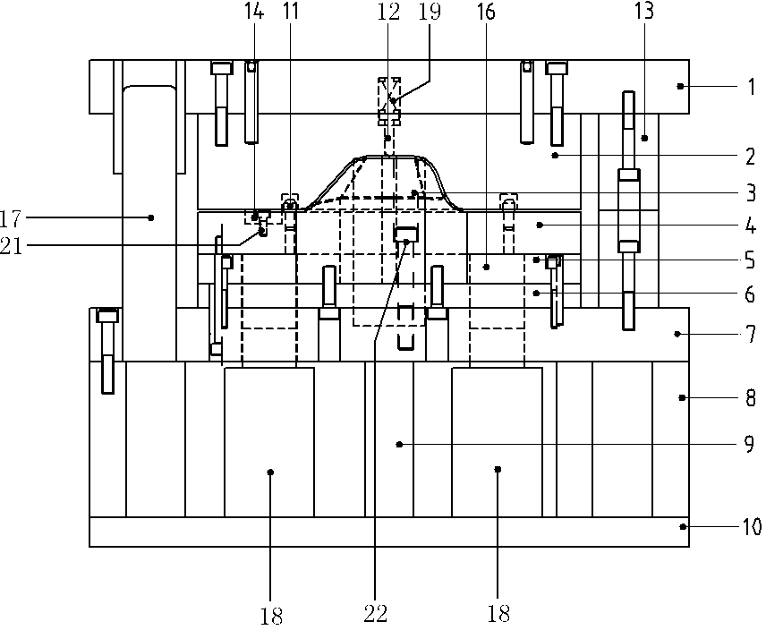
[0016] See image 3 , Figure 4 and Figure 5 , the preforming mold of the present invention comprises an upper mold structure and a lower mold structure, the upper mold structure includes an upper template 1 and a forming upper mold 2, the upper template 1 is equipped with a forming upper mold 2, and the lower mold structure includes a lower template 7, a lower backing plate 6. The lower fixing plate 5 and the forming lower mold 3, the lower fixing plate 5 is installed on the lower template 7 through the lower backing plate 6, the forming lower mold 3 is installed on the lower fixing plate, 5, the forming upper mold 2 and the forming lower mold 3 The lower mold plate 7 is mounted on the mounting plate 10 through the lower mold feet 8, 9, the upper mold structure and the lower mold structure are guided by the independent sliding guide 17 to close the mold, and the lower mold structure also includes the binder plate 4, the binder plate 4 Installed on the lower fixed plate 5...


PUM


Abstract

The invention provides a pre-forming die of an automobile engine exhaust system manifold and solves the problem that the existing forming dies are insufficient in workpiece compression. The pre-forming die is characterized in that a lower die structure comprise a pressing plate which is mounted on a lower fixing plate, a forming lower die is mounted in the pressing plate and connected with the lower fixing plate, an ejector pin is mounted in the lower fixing plate, the ejector pin vertically penetrates the lower fixing plate, a lower base plate and a lower die plate, and the lower portion of the ejector pin is connected with the guide rod of a nitrogen cylinder which is mounted on a mounting plate. By the pre-forming die, in-place pre-forming of workpieces through one-step punching is guaranteed.

Description

technical field [0001] The invention relates to the field of stamping processing of components of an automobile engine exhaust system, in particular to a preformed mold for a manifold of an automobile engine exhaust system. Background technique [0002] An automobile engine exhaust system manifold, which is formed by stretching the upper half shell and the lower half shell together, then cutting them, and then welding them together, because the upper half shell and the lower half shell are stretched together The forming surface height is high and the forming surface is complex. One-time direct stamping and stretching can easily lead to cracking of the shell. Therefore, the workpiece needs to be preformed first. The schematic diagram of the preformed workpiece structure is shown in figure 1 and figure 2 , due to the high tensile height and large stretching area of ​​the pre-formed material, there will be a problem that the workpiece is not formed properly due to insuffi...

Claims


Application Information

Patent Timeline
Patent Type & Authority Applications(China)
IPC IPC(8): B21D37/10B21D37/12
Inventor 白瑛曹一枢黄健
Owner WUXI DAWN DIE & STAMPING
Why Eureka
Try Eureka