Pipe bending machine

A pipe bending machine and pipe bending technology, applied in metal processing equipment, forming tools, manufacturing tools, etc., can solve problems such as large operating errors, affecting work efficiency, wasting manpower, etc., to reduce production costs, improve work efficiency, and improve The effect of production efficiency

Active Publication Date: 2014-06-25
OMS MASCH CO LTD
View PDF8 Cites 25 Cited by
  • Summary
  • Abstract
  • Description
  • Claims
  • Application Information

AI Technical Summary

Problems solved by technology

[0002] At present, the pipe bending machines on the market have generally realized the integrated production process of feeding, cutting, bending and unloading, but such pipe bending machines still have the following deficiencies: 1. Complete pipe bending on smaller-sized material pipes Finally, it is difficult for the unloading manipulator to grab the material tube, and at this time it is necessary to manually take out the material tube, which seriously affects the work efficiency; 2. The unloading mechanism can only discharge the curved material tubes of all specifications into the same material frame , Bending tubes of different specifications cannot be picked up by the unloading manipulator and placed in different places. Subsequent manual sorting of all the specifications of the bent material tubes grabbed by the unloading manipulator is low in work efficiency and wastes manpower; 3. The structure of the driving device that drives the clamping mold and the former close to the bending mold of the bending mechanism is complicated, and the operation error is large; 4. The existing pipe bending machine occupies a large area, the structure is not compact, and the space is wasted

Method used


Image

  • Pipe bending machine
  • Pipe bending machine
  • Pipe bending machine

Examples


Embodiment Construction

[0041] The present invention will be further described below in conjunction with accompanying drawing:

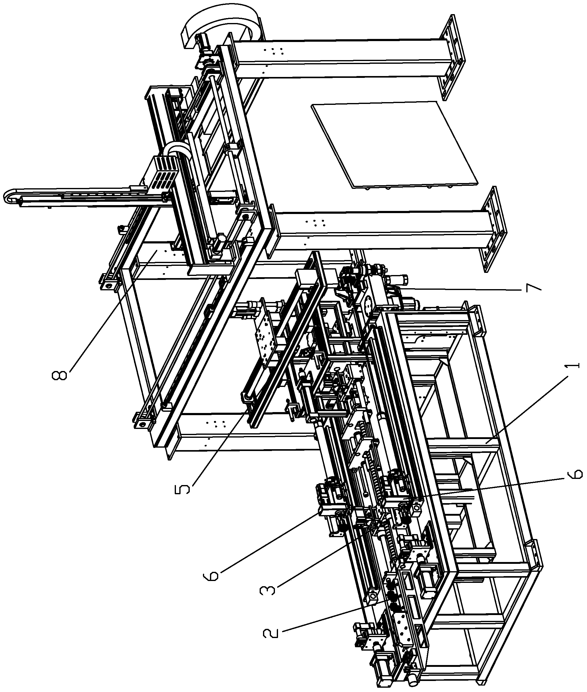
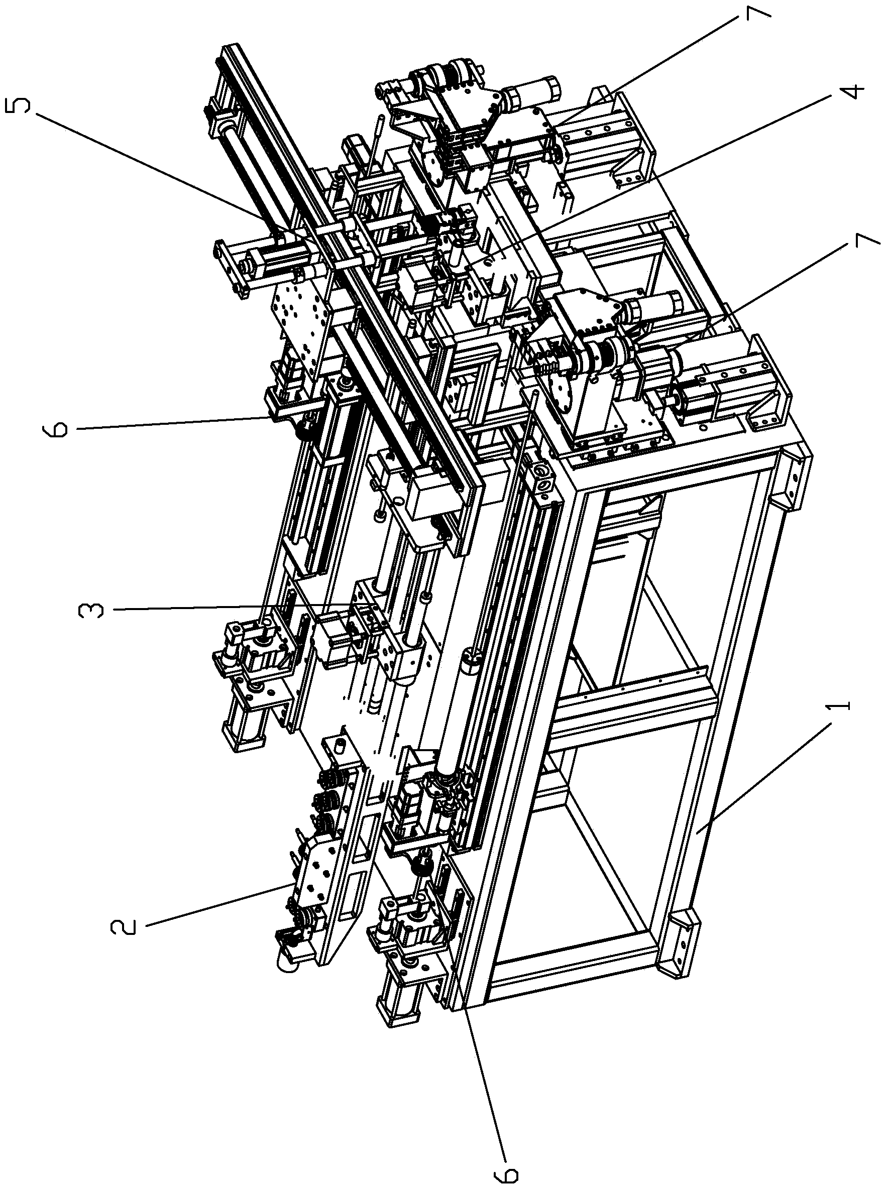
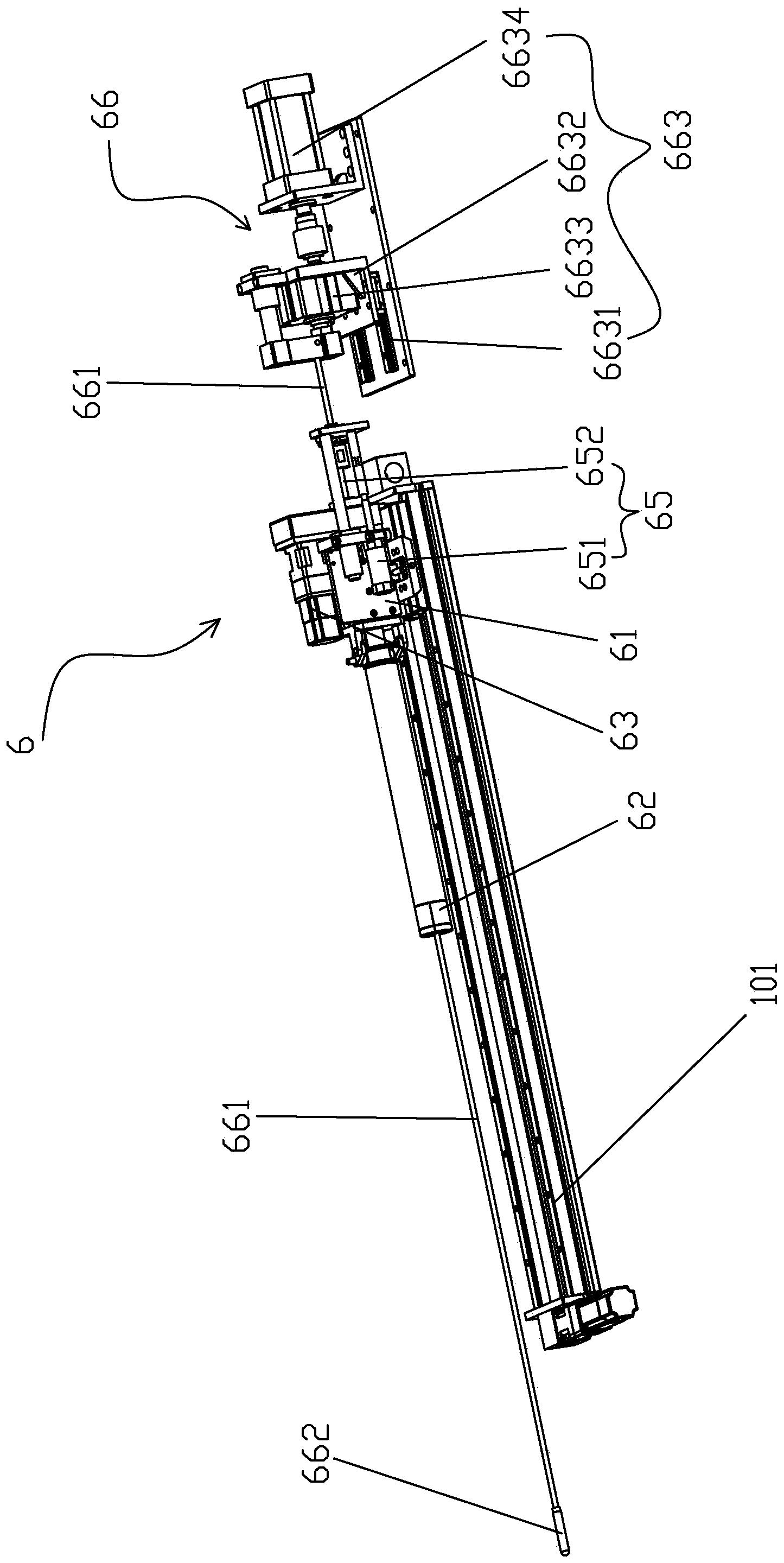
[0042] Such as Figure 1 to Figure 5 As shown, a pipe bending machine includes a frame 1, the frame 1 is provided with a straightening mechanism 2 capable of straightening the material tube, and the output end of the straightening mechanism 2 is provided with a feeding mechanism 3 , the output end of the described feeding mechanism 3 is provided with a material opening mechanism 4, the output end of the described material opening mechanism 4 is provided with a material shifting mechanism 5, and the described material moving mechanism 5 can move the described material opening mechanism 4 The cut material pipe is transferred to the elbow feeding mechanism 6 located next to the feeding mechanism 3, and the output end of the elbow feeding mechanism 6 is provided with a bending material that can bend the material pipe it sends. Mechanism 7, the output end of the material bendin...


PUM


Abstract

The invention discloses a pipe bending machine which comprises a rack. A straightening mechanism is arranged on the rack, a feeding mechanism is arranged at an output end of the straightening mechanism, a cutting mechanism is arranged at an output end of the feeding mechanism, a moving mechanism is arranged at an output end of the cutting mechanism and can move material pipes cut by the cutting mechanism to a pipe bending feeding mechanism arranged beside the feeding mechanism, a bending mechanism capable of bending the material pipes fed by the pipe bending feeding mechanism is arranged at an output end of the pipe bending feeding mechanism, a discharging mechanism for discharging is arranged at an output end of the bending mechanism, the pipe bending feeding mechanism comprises a sliding rail, a feeding seat is arranged on the sliding rail, a rotating clamping head, a rotating positioning motor and a clamping cylinder driving the rotating positioning head to clamp the material pipes is arranged on the feeding seat, and a pushing device capable of pushing the bent material pipes out of the rotating clamping head is arranged on the feeding seat. By the pipe bending machine, small-specification bend material pipes that a discharging manipulator cannot grab can be pushed out of the pipe bending machine to complete automatic discharging, so that working efficiency is improved, manpower is saved, and production cost is lowered.

Description

【Technical field】 [0001] The invention relates to a pipe bending machine. 【Background technique】 [0002] At present, the pipe bending machines on the market have generally realized the integrated production process of feeding, cutting, pipe bending and unloading, but such pipe bending machines still have the following deficiencies: 1. Complete the pipe bending on smaller-sized material pipes Finally, it is difficult for the unloading manipulator to grab the material tube, and at this time it is necessary to manually take out the material tube, which seriously affects the work efficiency; 2. The unloading mechanism can only discharge the curved material tubes of all specifications into the same material frame , Bending tubes of different specifications cannot be picked up by the unloading manipulator and placed in different places. Subsequent manual sorting of all the specifications of the bent material tubes grabbed by the unloading manipulator is required, which results in...

Claims


Application Information

Patent Timeline
Patent Type & Authority Applications(China)
IPC IPC(8): B21D45/02B21D37/10B21D7/00
Inventor 龙晓斌何汉强宋俊锡陈敬之
Owner OMS MASCH CO LTD
Why Eureka
Try Eureka