Clamping device for machining and positioning of pincers of disc brakes

A disc brake and clamping device technology, which is applied in positioning devices, clamping devices, manufacturing tools, etc., can solve the problems of inability to meet the machining accuracy requirements of the caliper body, low work efficiency, and low degree of automation, so as to save human resources The effect of high cost, high processing efficiency and high processing accuracy

Active Publication Date: 2014-06-25
JIANGSU HENGLI BRAKE MFG +1
View PDF5 Cites 13 Cited by
  • Summary
  • Abstract
  • Description
  • Claims
  • Application Information

AI Technical Summary

Problems solved by technology

[0007] The technical problem solved by the present invention is to overcome the traditional clamping device. In one clamping, there are few surfaces that can be processed, and manual multiple clamping is required, resulting in low processing accuracy, which cannot meet the processing accuracy requirements of the caliper body. Low, low degree of automation, time-consuming and labor-intensive problems

Method used


Image

  • Clamping device for machining and positioning of pincers of disc brakes
  • Clamping device for machining and positioning of pincers of disc brakes
  • Clamping device for machining and positioning of pincers of disc brakes

Examples


Embodiment Construction

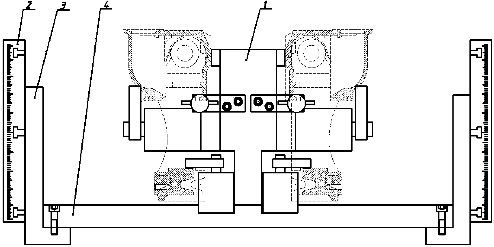
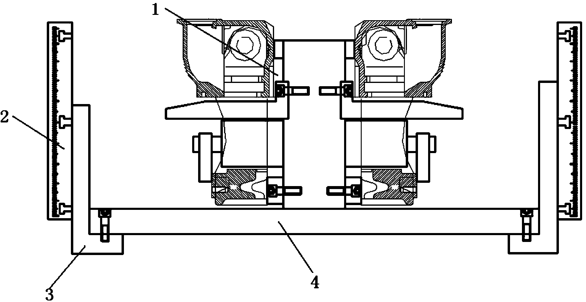
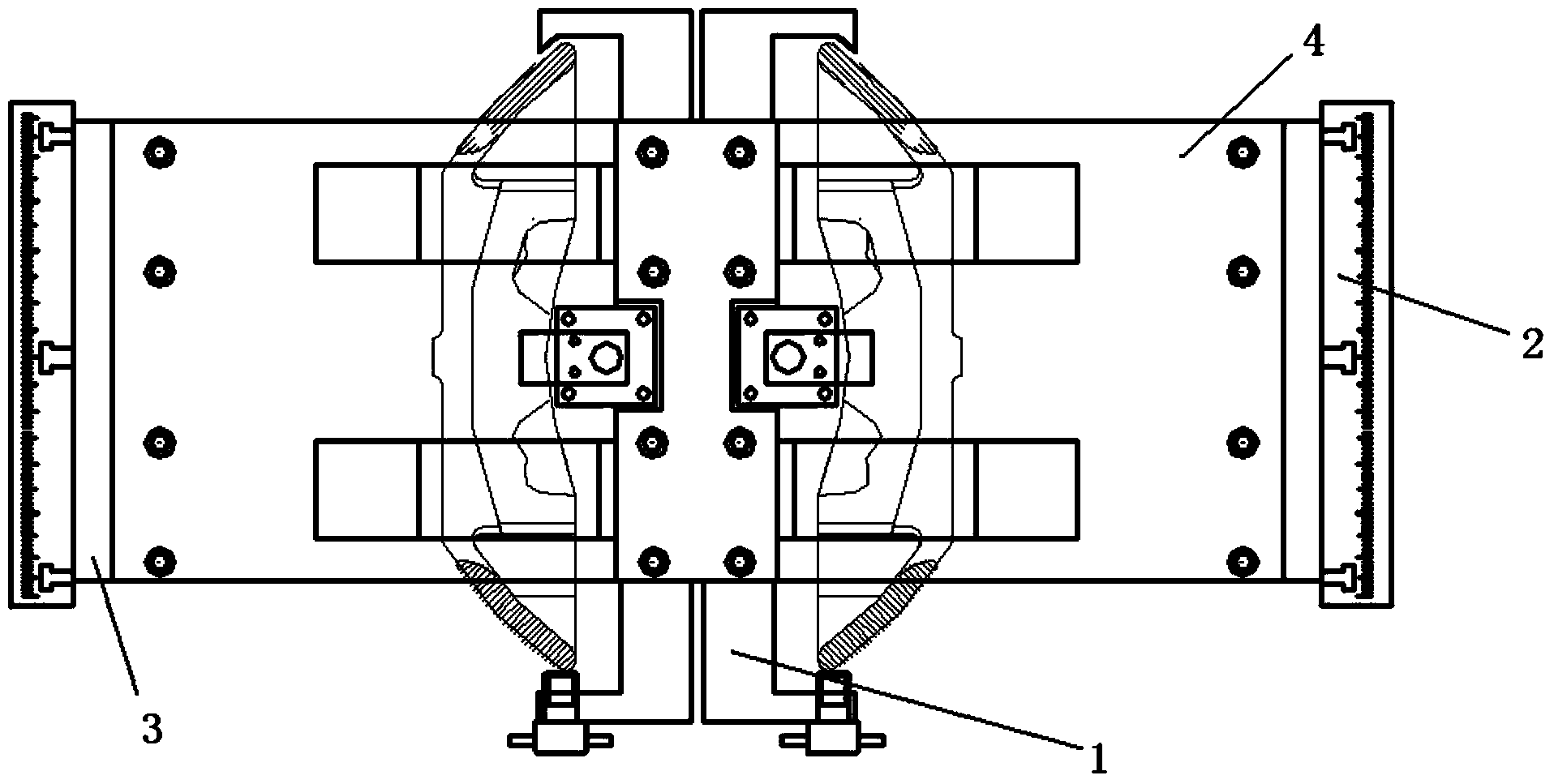
[0039] The present invention will be further described below in conjunction with the accompanying drawings.

[0040] Such as figure 1 , figure 2 and image 3 As shown, the clamping device used for the processing and positioning of the disc brake caliper of the present invention includes an intermediate plate 1, and two sets of clamping mechanisms are symmetrically arranged on both sides of the intermediate plate 1, and the intermediate plate 1 is a combination of two sets of clamping mechanisms. The carrier, the middle plate 1, is in the shape of a cuboid, and a cuboid groove is respectively provided at the lower part of the center line of the two sides, which is used to place the rotating lower oil cylinder 7 of the clamping mechanism, and two cuboid grooves are respectively provided on both sides of the center line for placing the clips. The wedge-shaped bracket 8 of the holding mechanism, the bottom of the middle plate 1 is provided with a bridge plate 4, and the two sid...


PUM


Abstract

The invention discloses a clamping device for machining and positioning of pincers of disc brakes. The clamping device comprises an intermediate plate, two groups of clamping mechanisms are symmetrically arranged on two lateral sides of the intermediate plate respectively, index plates and L-blocks are symmetrically arranged on two sides of a bridge plate which is arranged at the bottom of the intermediate plate, and the index plates are fixed onto the bridge plate through the L-blocks. Each clamping mechanism comprises a supporting block, an upper rotary cylinder, a lower rotary cylinder, a clamping unit and a positioning unit in sequential distribution from top to bottom, and a wedged support, a middle rotary cylinder and a positioning block are sequentially distributed from top to bottom and symmetrically arranged on two sides of each upper rotary cylinder and the corresponding lower rotary cylinder. The wedged supports are used for supporting and positioning the pincers of the disc brakes, and the upper rotary cylinders, the lower rotary cylinders and the middle rotary cylinders control moving degrees of freedom of the pincers of the disc brakes in the X-axial, Y-axial and Z-axial directions. The clamping units are positioned on the front side of the intermediate plate, and the positioning units are positioned on the rear side of the intermediate plate. The clamping device is capable of clamping two pincers at one time and realizing workpiece rotation to machine different surfaces and is high in machining precision and effectiveness and good in application prospect.

Description

technical field [0001] The invention relates to the technical field of mechanical clamps, in particular to a clamping device for processing and positioning disc brake caliper bodies. Background technique [0002] Disc brakes are widely used in automobiles because of their advantages such as large braking torque, good thermal stability, good braking performance and water stability, small size, small wear, easy automatic adjustment of gaps, and convenient maintenance operations. , shipbuilding and other industries. [0003] As an important part of the disc brake, the caliper has a complex structure, high machining accuracy and strict technical requirements. It is difficult to meet the technical requirements of the product with general-purpose machine tools. The traditional clamping device for the processing and positioning of the disc brake caliper has the following technologies defect: [0004] (1) There is only one positioning and clamping device on a machine tool, so only...

Claims


Application Information

Patent Timeline
Patent Type & Authority Applications(China)
IPC IPC(8): B23Q3/08
CPCB23Q3/061B23Q3/062B23Q3/082B23Q2703/04B23Q2703/08B23Q2703/10
Inventor 徐旗钊张建姚凯郑继飞朱永梅刘焱张阳唐文献
Owner JIANGSU HENGLI BRAKE MFG
Why Eureka
Try Eureka