Hydraulic floating centering and clamping transmission device

A transmission device, hydraulic clamping technology, applied in the direction of positioning device, clamping, support, etc., can solve the problems of difficulty in completing order tasks on time, rising manufacturing costs, labor recruitment and management difficulties, etc. Convenience and high productivity

Inactive Publication Date: 2014-06-25
ZHEJIANG UNIV
View PDF8 Cites 12 Cited by
  • Summary
  • Abstract
  • Description
  • Claims
  • Application Information

AI Technical Summary

Problems solved by technology

With the deterioration of factors such as rising labor costs and RMB appreciation, my country's low-cost manufacturing advantages will gradually lose, and a seri

Method used


Image

  • Hydraulic floating centering and clamping transmission device
  • Hydraulic floating centering and clamping transmission device
  • Hydraulic floating centering and clamping transmission device

Examples


Example Embodiment

[0020] The present invention will be further explained below with reference to the drawings and examples.

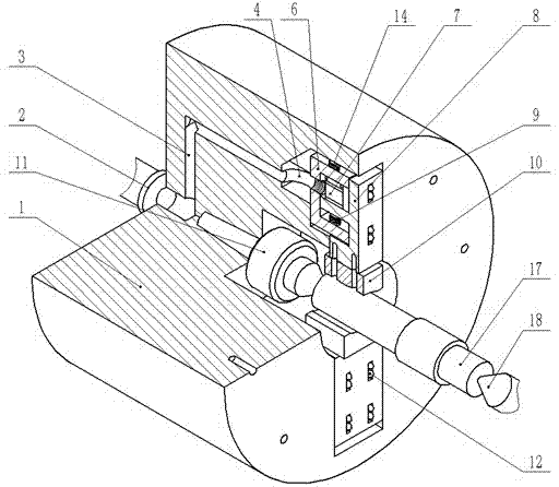
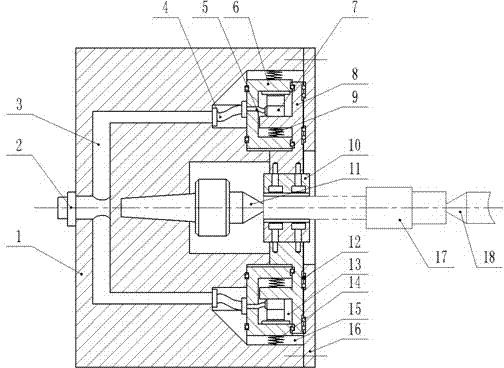
[0021] Such as figure 1 , figure 2 As shown, the present invention includes a chuck body 1 and a rotary joint 2, two semicircular chucks 10, a center 11, an end cover 16 and two hydraulic clamping devices with the same structure. The center hole of the cylindrical chuck body 1 is equipped with a center 11, the end of the center 11 is fixed in the tapered hole of the chuck body 1, and the center hole of the chuck body 1 with the tip of the center outwards is equipped with a symmetrically arranged semicircle. The chuck, the chuck body 1 outside the two semicircular chucks 10 has rectangular holes symmetrically opened, and the two rectangular holes are respectively equipped with hydraulic clamping devices with the same structure and opposite installation directions, and two hydraulic clamping devices They are respectively fixedly connected with their respective semicircular c...


PUM


Abstract

The invention discloses a hydraulic floating centering and clamping transmission device. A center is installed in a center hole of a cylindrical chuck body. Symmetrically-arranged semicircular clamping heads are installed in the positions, outside the tip of the center, of the center hole of the chuck body. Rectangular holes are symmetrically formed in the positions, outside the two semicircular clamping heads, of the chuck body. Hydraulic clamping devices which are the same in structure and opposite in installing direction are installed in the corresponding rectangular holes respectively and fixedly connected with the corresponding semicircular clamping heads respectively. An end cover and the outer sides of the two hydraulic clamping devices form a rolling pair. Hydraulic cylinders in the two hydraulic clamping devices are both connected to a center oil port of the chuck body through respective hoses, respective flexible connectors and a hydraulic pipeline on the chuck body respectively. Rotating connectors are connected with the center oil port of the chuck body in a threaded mode. According to the machining characteristics of shaft parts, the shaft parts can be automatically centered and clamped. A mechanical arm and a numerical control machine tool are matched, the shaft parts can be automatically produced, the influence of human factors is reduced, and product quality and production efficiency are improved.

Description

technical field [0001] The invention relates to a hydraulic clamping transmission device, in particular to a hydraulic floating centering clamping transmission device for machining parts with high coaxiality requirements. Background technique [0002] Shaft parts are a general term for a type of parts whose main body is a rotary structure, with small radial dimensions and large axial dimensions. The parts have large batches and many specifications, such as output shafts and other parts that are widely used in the automotive industry. In the manufacturing and processing of the traditional automobile industry, due to the high-precision requirements of some shaft parts, such as the high coaxiality requirements of the stepped shaft, it is necessary to adopt a variety of auxiliary methods. At present, the following three auxiliary methods are used in production: 1) Additional additional auxiliary processes, such as pre-turning the outer circle, etc., in this method, the inc...

Claims


Application Information

Patent Timeline
IPC IPC(8): B23Q3/12
CPCB23Q3/00
Inventor 丁正龙徐月同傅建中吴森洋王郑拓
Owner ZHEJIANG UNIV
Why Eureka
Try Eureka