Pneumatic punching machine

A pneumatic punching and punching technology, which is applied in metal processing and other directions, can solve the problems of ignoring the positioning of stamped parts, and achieve the effects of high work efficiency, accurate placement, and convenient disassembly

Inactive Publication Date: 2014-06-25
江苏东方印务有限公司
View PDF6 Cites 13 Cited by
  • Summary
  • Abstract
  • Description
  • Claims
  • Application Information

AI Technical Summary

Problems solved by technology

The application has a simple structure and high work efficiency, and can simultaneously punch multiple stamped parts at one time; the punching die can be replaced, which can meet various punching needs, save labor costs, reduce labor intensity, simple structure, and easy operation Convenience; but the application still ignores the problem of accurate positioning of the stamped parts

Method used


Image

  • Pneumatic punching machine
  • Pneumatic punching machine

Examples


Embodiment

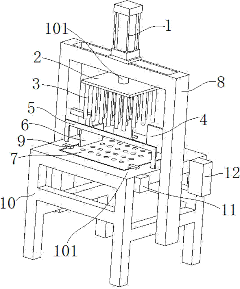
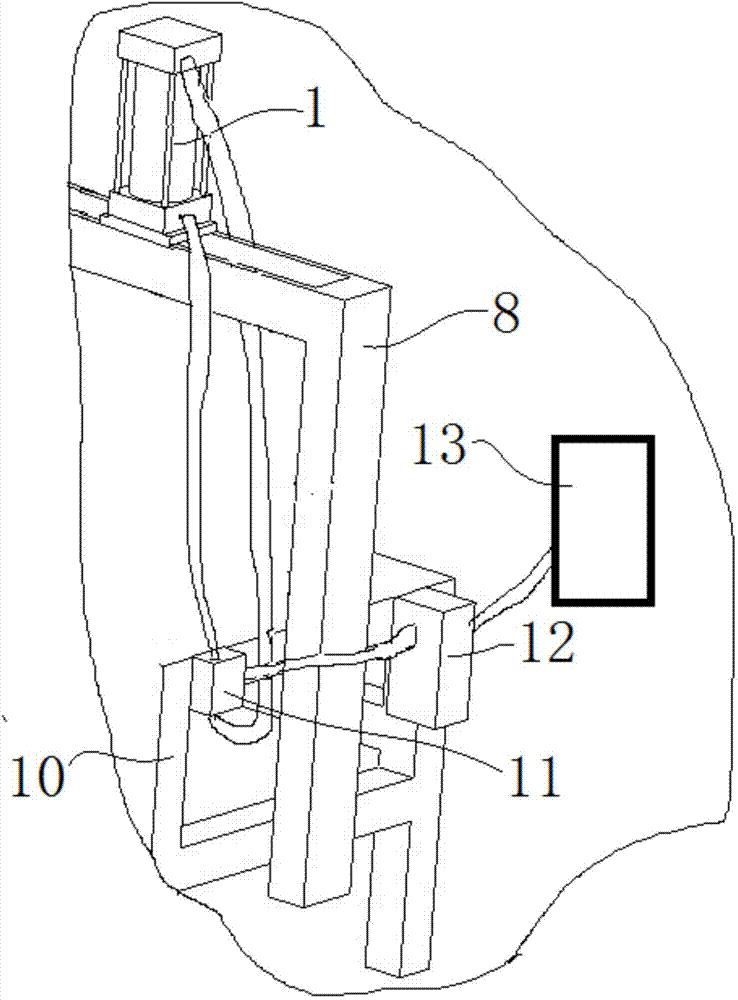
[0025] combine figure 1 and figure 2 , a pneumatic punching machine of the present embodiment, comprising an upper template 2, a punch 3, a bolt locking mechanism 10, a workbench 9, a manual reversing valve 11 fixed on the side of the workbench 9, and a manual reversing valve fixed on the side of the workbench 9 The pressure regulating valve 12 and the positioning device, the upper part of the workbench 9 is the work platform 901; the work platform 901 is embedded with a die 7, and the die 7 is fixed on the workbench 9 through the bolt locking mechanism 10, so that the installation is stable , and it is easy to disassemble; a positioning device for positioning the stamped part is fixed on the working platform 901, which makes the placement of the stamped part more accurate, reduces the stamping error rate, and saves costs; the positioning device includes a positioning device for positioning the width of the stamped part The first positioning piece 4 in the direction, the sec...


PUM


Abstract

The invention discloses a pneumatic punching machine, and belongs to the field of punching machines. The pneumatic punching machine comprises an upper die plate, a punch, a bolt locking mechanism, a worktable, a manual reversing valve fixed to a lateral surface of the worktable, a pressure regulating valve and a positioning device, wherein the pressure regulating valve and the positioning device are fixed to another lateral surface of the worktable, the upper portion of the worktable is a work platform, a concave die is embedded in the work platform and fixed to the worktable through the bolt locking mechanism, the worktable is fixedly connected with the positioning device used for positioning a workpiece to be punched, a machine frame is fixedly installed on the worktable, an air cylinder is installed at the top end of the machine frame, a piston rod of the air cylinder is fixedly connected with the upper die plate vertically moving relative to the machine frame, the upper die plate is provided with the punch corresponding to the concave die, the air cylinder is communicated with the pressure regulating valve through the manual reversing valve, and the pressure regulating valve is communicated with an air compressor. The pneumatic punching machine is convenient to operate, high in work efficiency and accurate in positioning, and lowers punching error rate.

Description

technical field [0001] The present invention relates to a punching machine, more particularly, to a pneumatic punching machine. Background technique [0002] The punching after die-cutting of various stamped parts and corrugated stamped parts in the printing industry is generally done manually, which has low work efficiency, poor punching quality, and often easily injures the operator, with low safety performance. [0003] After searching, the technical scheme for improving the existing punching machine has been published, such as Chinese patent number ZL201120525490.9, the date of authorization announcement is October 3, 2012, the name of the invention is: automatic punching machine, the application The utility model relates to an automatic punching machine, which comprises a frame. A workbench is arranged on the frame. A cylinder is arranged above the workbench. A punching die is fixedly connected to the end of a piston rod of the cylinder, and the cylinder is connected to...

Claims


Application Information

Patent Timeline
Patent Type & Authority Applications(China)
IPC IPC(8): B26F1/02B26D7/01B26D5/12
Inventor 芮勇周乃武
Owner 江苏东方印务有限公司
Why Eureka
Try Eureka