Automatic tape attaching device and method

A driving device and tape technology, applied in lamination devices, chemical instruments and methods, transportation and packaging, etc., can solve the problems of low practicability, narrow application scope, and inability to achieve full automation, and achieve improved processing yield, The effect of improving work efficiency and wide application value

Active Publication Date: 2014-06-25
BOE TECH GRP CO LTD +1
View PDF8 Cites 5 Cited by
  • Summary
  • Abstract
  • Description
  • Claims
  • Application Information

AI Technical Summary

Problems solved by technology

[0005] 1. Manual assistance is still required in the practice process, and full automation cannot be achieved;
[0006] 2. It is only suitable for attaching light-shielding tapes to s

Method used


Image

  • Automatic tape attaching device and method
  • Automatic tape attaching device and method
  • Automatic tape attaching device and method

Examples


Example Embodiment

[0076] Example 1

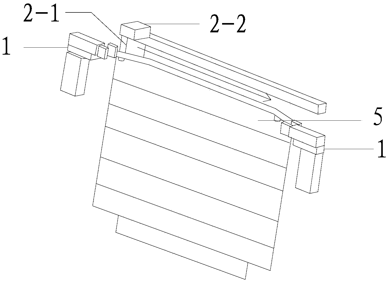
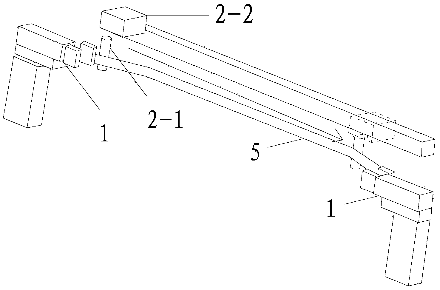
[0077] The tape automatic attaching device described in this embodiment includes three groups of subunits, and each group of subunits includes a tape clamping cylinder 1, a tape stripping mechanism, and a tape absorbing / attaching mechanism.

[0078] like figure 1 and figure 2 As shown, the adhesive tape clamping cylinder 1 fixes the adhesive tape 5, and the adhesive tape peeling mechanism is located at any starting end of the adhesive tape 5; constitute. Adhesive tape folder clamps a corner of adhesive tape 5, and adhesive tape stripping cylinder 2-2 drives stripping bar 2-1 to move from the starting end of adhesive tape to the end, completes adhesive tape stripping.

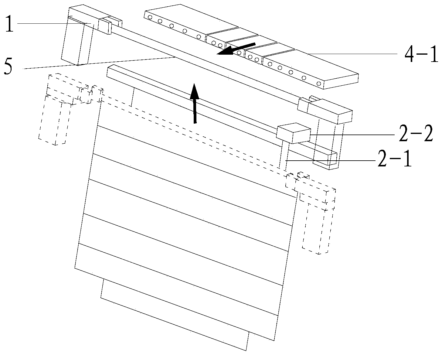
[0079] Since the four sides of the light guide plate 6 in this embodiment except the light-incident side, the rear side is a regular surface, and the left and right sides are irregular surfaces, therefore, in this embodiment, the subunits corresponding to the irregular left and right sides...

Example Embodiment

[0081] Example 2

[0082] Compared with Embodiment 1, the difference lies in that the three sides of the light guide plate 6 in this embodiment are irregular, and among the three groups of subunits of the automatic tape sticking device, each group of subunits includes a tape clamping cylinder, Tape peeling mechanism, tape cutting mechanism and tape adsorption / attachment mechanism.

Example Embodiment

[0083] Example 3

[0084] Compared with Example 1, the difference is only that, as Figure 4 As shown, the tape cutting mechanism described in this embodiment is a single-blade cutting mechanism, including a slidable blade 3-1, a blade control cylinder 3-2 and a blade positioning shaft for driving and supporting the sliding of the blade 3-1 3-3. During the use of the single-blade cutting mechanism, the slidable blade 3-1 is driven by the blade control cylinder 3-2 to slide along the blade positioning shaft 3-3, and automatically cuts the tapes sequentially at designated positions.


PUM


Abstract

The invention discloses an automatic tape attaching device which comprises at least one group of subunits and at least one group of tape cutting mechanisms, wherein each group of subunits comprises a tape clamping air cylinder, a tape stripping mechanism and a tape adsorbing/attaching mechanism; each tape clamping air cylinder is used for fixing a tape; each tape stripping mechanism is arranged at any starting end of the tape; each tape adsorbing/attaching mechanism comprises a tape push rod opposite to the tape and a drive device of the tape push rod. According to the automatic tape attaching device, the tapes of regular/irregular light guide plates can be automatically cut and attached, so that the working efficiency is greatly improved; workers do not need to be in direct contact with the light guide plates, so that the scratch on the light guide plates is effectively avoided and the processing yield can be increased.

Description

technical field [0001] The invention relates to an automatic device, in particular to an automatic adhesive tape sticking device and method. Background technique [0002] Light-shielding tape usually needs to be attached around the light guide plate to reduce light loss. The traditional method is to attach it manually, which is labor-intensive and the processing efficiency is not high; and because the upper surface of the light guide plate usually has a very fine prism structure, Therefore, it is easy to cause scratches during operation. [0003] The prior art CN202102163U discloses an improved technical solution, that is, a tape attachment mold for a light guide plate, which includes a base, a base plate rotatably connected to the base, and a base plate arranged on the base plate for positioning The positioning mechanism of the light guide plate, the clamping mechanism set on the light guide plate for clamping and fixing the light guide plate, the bottom plate has a slide ...

Claims


Application Information

Patent Timeline
IPC IPC(8): B32B37/00B32B38/10B65H35/06
Inventor 严志伟曹春雷
Owner BOE TECH GRP CO LTD
Why Eureka
Try Eureka