Pile foundation dynamic load testing system based on optical fiber grating and testing method of pile foundation dynamic load testing system

A fiber grating and test system technology, which is applied in the test of infrastructure, infrastructure engineering, construction, etc., can solve the problems of lagging and insufficient evaluation standards, reduce the risk of equipment damage, reduce the difficulty, and increase stability. Effect

Active Publication Date: 2014-06-25
HOHAI UNIV
View PDF5 Cites 11 Cited by
  • Summary
  • Abstract
  • Description
  • Claims
  • Application Information

AI Technical Summary

Problems solved by technology

Due to the insufficiency of dynamic load-related tests and theoretical research, the current understanding of the bearing and deformation characteristics of pile foundations under dynamic loads is far from enough, and the existing evaluation standards lag far behind engineering practice. To guide engineering design, it is necessary to carry out systematic experiments and theoretical studies on the characteristics of pile foundations under dynamic loads, and to deepen the understanding of the bearing and deformation mechanism of pile foundations under dynamic loads

Method used


Image

  • Pile foundation dynamic load testing system based on optical fiber grating and testing method of pile foundation dynamic load testing system
  • Pile foundation dynamic load testing system based on optical fiber grating and testing method of pile foundation dynamic load testing system
  • Pile foundation dynamic load testing system based on optical fiber grating and testing method of pile foundation dynamic load testing system

Examples


Embodiment Construction

[0022] The present invention will be described in detail below in conjunction with the examples. It should be understood that these examples are only used to illustrate the present invention and are not intended to limit the scope of the present invention. In addition, it should be understood that after reading the teachings of the present invention, those skilled in the art can make various changes or modifications to the present invention, and these equivalent forms also fall within the scope defined by the appended claims of the present application.

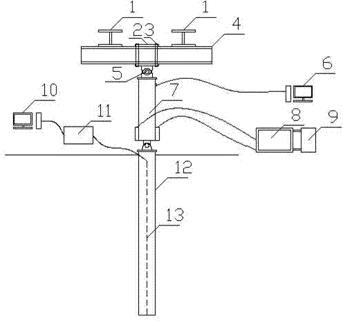
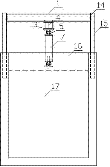
[0023] The fiber grating-based pile foundation dynamic load test system of the present embodiment is as follows: figure 1 and figure 2 Shown, comprise reaction force frame, power loading device and soil holding tank 17. Wherein the reaction frame includes a pair of gate-shaped brackets arranged in parallel, which are formed by connecting channel steel columns 15 and I-beam upper beams 1 through high-strength bolts 14, and t...


PUM


Abstract

The invention discloses a pile foundation dynamic load testing system based on an optical fiber grating and a testing method of the pile foundation dynamic load testing system. The testing system comprises a counterforce frame device, a power loading device, a soil containing tank and a monitoring device. The testing method includes the steps that various vibration waves are simulated through the set of power loading device and exerted on a foundation pile, and stress strain deformation conditions of the foundation pile are detected through the sensing optical fiber grating arranged in the foundation pile. The counterforce frame device and the soil containing tank are cast together to ensure that counterforce is transmitted stably and reliably; the power loading device can accurately control loading wave forms and loads in the power testing process; the monitoring device is high in response speed and can achieve remote monitor, and the sensing optical fiber grating has little influence on a pile body.

Description

technical field [0001] The invention relates to a test device and a test method of a foundation structure, in particular to a pile foundation dynamic load test system and a test method based on an optical fiber grating. Background technique [0002] In the existing related projects, the pile foundation design method under the static force is mostly used in the design, and the influence of the vibration load is rarely considered. The bearing capacity can only be used as the design control standard, and the method of greatly increasing the bearing capacity as a safety reserve is designed. . In recent years, with the rapid development of my country's high-speed railway construction, the requirements for high-speed, high comfort, high safety, and high-density continuous operation of high-speed railways have become higher and higher. Require. When a high-speed train passes the bridge, due to the dynamic action, the dynamic response of the pier body is significant. At the same ti...

Claims


Application Information

Patent Timeline
Patent Type & Authority Applications(China)
IPC IPC(8): E02D33/00
Inventor 高磊刘汉龙孔纲强丁选明余湘娟陈晖东
Owner HOHAI UNIV
Why Eureka
Try Eureka