Concealed type rotary lock cylinder and unlocking key

A rotary lock cylinder, hidden technology, applied in the field of locks and keys suitable for the locks, to achieve the effect of strong unlocking feel and flexible application

Active Publication Date: 2014-06-25
江苏扬先科技有限公司
View PDF7 Cites 6 Cited by
  • Summary
  • Abstract
  • Description
  • Claims
  • Application Information

AI Technical Summary

Problems solved by technology

However, this technical solution is only applicable to the locking drive bolt structure using dovetail grooves

Method used


Image

  • Concealed type rotary lock cylinder and unlocking key
  • Concealed type rotary lock cylinder and unlocking key
  • Concealed type rotary lock cylinder and unlocking key

Examples


Embodiment 1

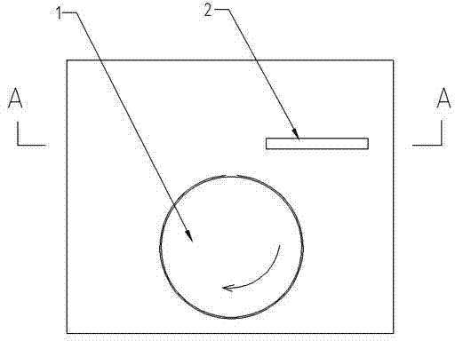
[0020] attached figure 1 Represents a hidden rotary lock cylinder, including a lock cylinder and a rotary locking drive bolt 1; the lock cylinder is a square block with a round through hole in the middle.

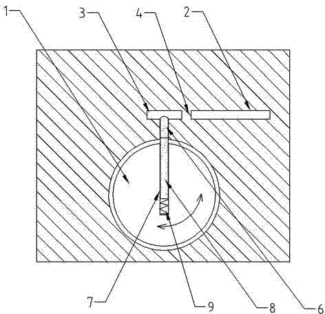
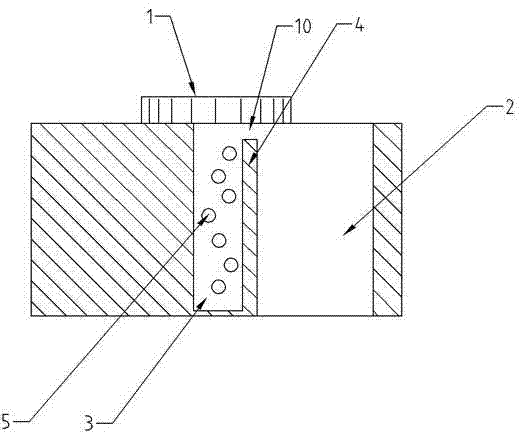
[0021] figure 2 and image 3 Indicates that the inside of the lock cylinder is provided with two strip-shaped tunnels with different widths in parallel; wherein, the wide strip-shaped tunnel 2 communicates with the front of the square block to form an insertion port; the narrow strip-shaped tunnel 3 is blocked from the front end of the square block; A partition wall 4 is formed in the lock core between the wide strip-shaped tunnel 2 and the narrow strip-shaped tunnel 3; there are 5 sections of marble holes in the narrow strip-shaped tunnel 3, and side column marbles 6 are arranged in each pinhole 5; The rotation locking driving bolt 1 is movably matched with the round through hole of the lock cylinder, so that the rotating locking driving bolt 1 can rotate relative to th...

Embodiment 2

[0025] A hidden rotary lock cylinder, comprising a lock cylinder and a rotary locking drive bolt 1; the lock cylinder is a cylindrical block with a round through hole in the middle. The inside of the lock cylinder is provided with two strip-shaped channels in parallel with different widths; wherein, the wide strip-shaped channel 2 communicates with the front of the cylindrical block to form an insertion port; the narrow strip-shaped channel 3 is blocked from the front end of the cylindrical block; A partition wall 4 is formed in the lock cylinder between the wide strip-shaped tunnel 2 and the narrow strip-shaped tunnel 3; there are 5 sections of marble holes in the narrow strip-shaped tunnel 3, and side column marbles 6 are arranged in each pinhole 5; The rotation locking driving bolt 1 and the round through hole of the lock cylinder are movably matched, so that the rotating locking driving bolt 1 can rotate relative to the lock cylinder to realize direct or indirect unlocking;...


PUM


Abstract

The invention relates to a concealed type rotary lock cylinder. The concealed type rotary lock cylinder comprises a lock cylinder body and a rotary locking drive bolt. The lock cylinder body is a square or cylindrical block with a round through hole in the middle. Two strip-shaped hole passages with different widths are formed inside the lock cylinder body in parallel. The wide strip-shaped hole passage is communicated with the front end face of the square or cylindrical block to form an insertion port. The narrow strip-shaped hole passage is not communicated with the front end face of the square or cylindrical block. A separation wall is formed between the wide strip-shaped hole passage and the narrow strip-shaped hole passage in the lock cylinder body. A marble hole section is arranged in the narrow strip-shaped hole passage, and a side column marble is arranged in each marble hole. The invention further relates to an unlocking key. The unlocking key is an inverted U-shaped strip plate and is matched with the concealed type rotary lock cylinder. According to the concealed type rotary lock cylinder and the unlocking key, lock cylinder components can not be seen from a tapered end or a shell of a lock body, so the purpose of preventing thieves from unlocking the lock by means of electric drills, forced unlocking tools, technical unlocking and the like can be achieved.

Description

technical field [0001] The invention relates to a lockset and a key suitable for the lockset, that is, a hidden rotary lock cylinder and an unlocking key. Background technique [0002] At present, the popular side post marble locks on the market, also known as "atomic" locks, use external force to push or rotate the lock cylinder containing the key socket to directly or indirectly unlock the lock. The key socket of this anti-theft lock cylinder There are many shapes such as: "once", "cross", "semi-arc", "plum blossom", "cylindrical" and so on. The whole body of the anti-theft lock is made of steel. On the surface, the anti-theft lock has very good anti-theft performance, and the market is also very popular. However, in real life, practical cases of theft of this lock often occur, and the lock cylinder is destroyed by a lawless person with a force-opening tool or a miniature electric drill, and the lock cylinder can be opened technically in a few seconds. Because this anti-...

Claims


Application Information

Patent Timeline
Patent Type & Authority Applications(China)
IPC IPC(8): E05B27/10E05B35/00E05B19/08
Inventor 陈小仁
Owner 江苏扬先科技有限公司
Why Eureka
Try Eureka