Impeller without hump

A hump and impeller technology, applied in the field of impellers with no hump head, can solve the problems of energy loss, unstable operation of the pump set, hump of the flow head curve, etc., and achieve the effect of reducing inlet backflow, avoiding energy loss, and expanding the operating area.

Active Publication Date: 2016-11-30
KSB SHANGHAI PUMP
View PDF5 Cites 0 Cited by
  • Summary
  • Abstract
  • Description
  • Claims
  • Application Information

AI Technical Summary

Problems solved by technology

[0003] The return flow at the inlet of the small flow area of ​​the vane pump will consume energy due to the generation of air vortices, so that the flow head curve will produce a hump (see Figure 5 The solid line curve in ), resulting in unstable operation of the pump set

Method used


Image

  • Impeller without hump
  • Impeller without hump
  • Impeller without hump

Examples


Embodiment Construction

[0018] Below in conjunction with the appendix of the embodiment picture Specific embodiments of the present invention will be described in detail.

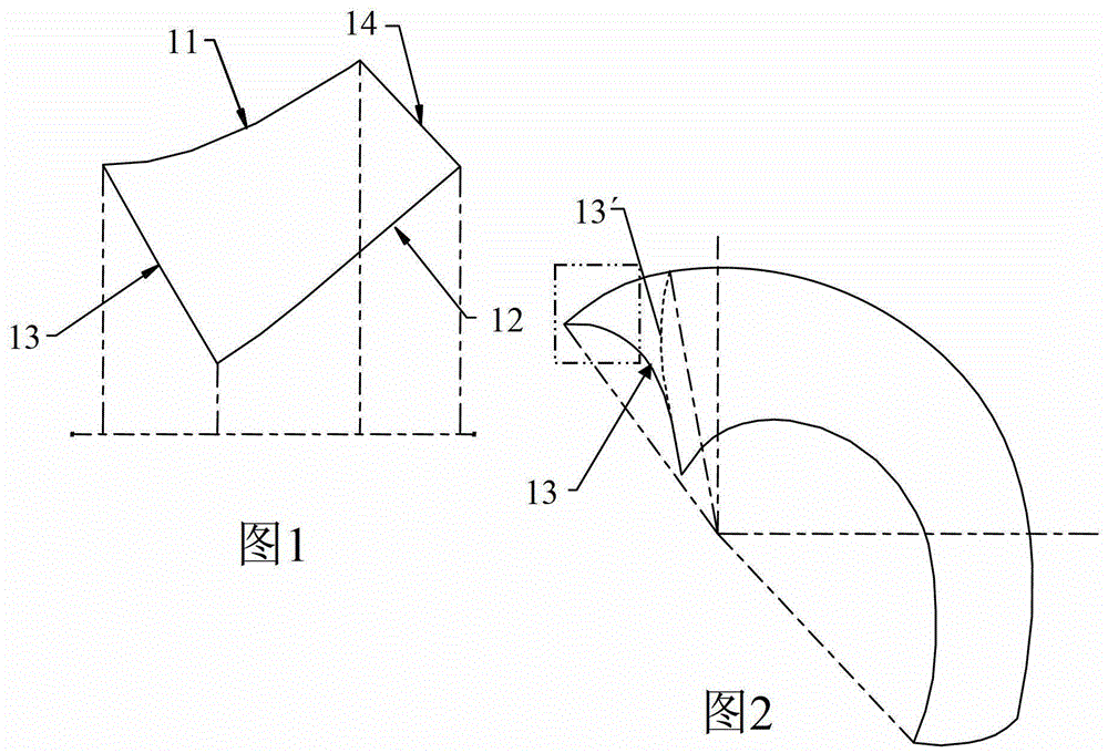
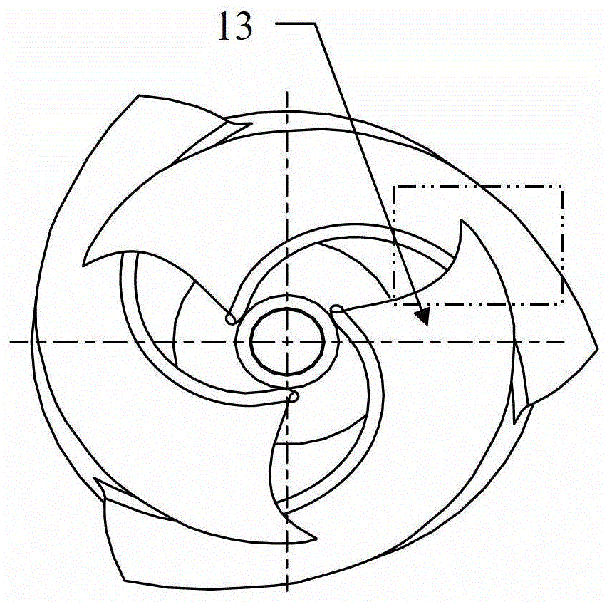
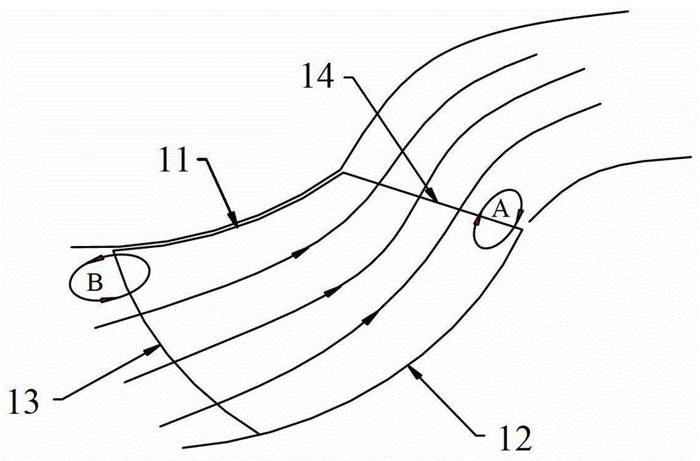
[0019] The impeller is located at the bottom of the volute of the pump, see Figure 1, the impeller includes a blade front cover 11, a blade rear cover 12, a hub and blades inside it, and multiple groups of blades are evenly distributed in front of the blades There is a fluid channel between the cover plate and the blade rear cover, and between the blades. The blade is firmly connected with the blade front cover and the blade rear cover by integral casting or welding. The blade rotates together through the shaft connected to the hub. The fluid flows along the working surface from the inlet side 13 of the blade to the outlet side 14 of the blade under the rotation of the blade, thereby realizing the function of pumping fluid.

[0020] As shown in Figures 1-3, the impeller with a head without a hump in the present invention adopts ...


PUM


Abstract

An impeller with a head without a hump, which relates to the impeller of a vane pump, which solves the problem of unstable operation of a pump set caused by a hump in the head of an existing impeller. A group of blades, the blades are integrally connected with the blade front cover plate and the blade rear cover plate, the blades rotate through the shaft connected to the hub, and there are fluid channels between the blades, and the fluid flows along the working surface from the blade inlet side to the blade outlet side, wherein : The outer edge of the inlet edge of each group of blades adopts a forward triangular structure near the front cover of the blade; each group of blades starts from the intersection point of the rear cover of the blade and the inlet edge of the blade, and at a distance of 0.6-1.0 times the length of the inlet edge, The angle of the inlet angle is less than 5 degrees. The impeller increases the length of the impeller streamline at the front cover of the blade, which can reduce the inlet return flow of the small flow area of ​​the vane pump, avoid the generation of vortex and energy loss, and the flow head will not produce a hump, which increases the stability of the pump operation.

Description

technical field [0001] The invention relates to an impeller of a vane pump, in particular to an impeller with a head without a hump. Background technique [0002] When the flow rate of the existing vane pump structure is less than the design flow rate, the liquid flow at the inlet of the pump is mostly concentrated at the rear cover of the vane due to the centrifugal force, forming a vortex area at the front cover of the vane, and backflow occurs, that is, the vane pump The inlet of the small flow area produces backflow (also called secondary backflow). The number of blades and the airfoil shape affect the flow point and degree of backflow. [0003] The return flow at the inlet of the small flow area of ​​the vane pump will consume energy due to the generation of air vortices, so that the flow head curve will produce a hump (see Figure 5 The solid line curve in ), resulting in unstable operation of the pump set. Contents of the invention [0004] The purpose of the pres...

Claims


Application Information

Patent Timeline
Patent Type & Authority Patents(China)
IPC IPC(8): F04D29/22F04D29/24
Inventor 周文朝张晓峰李海峰潘再兵
Owner KSB SHANGHAI PUMP
Why Eureka
Try Eureka